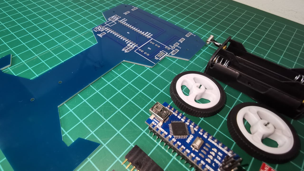
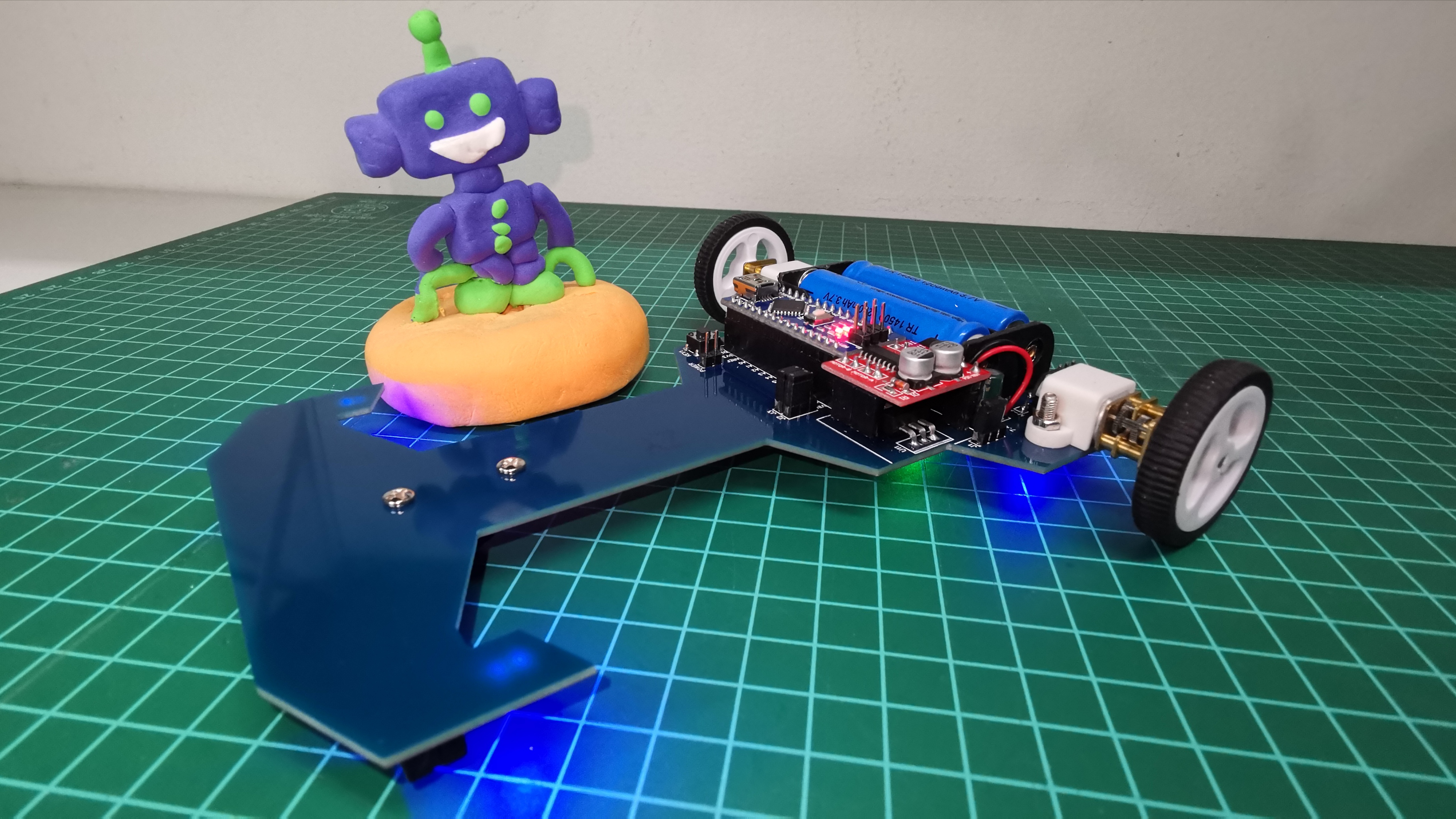
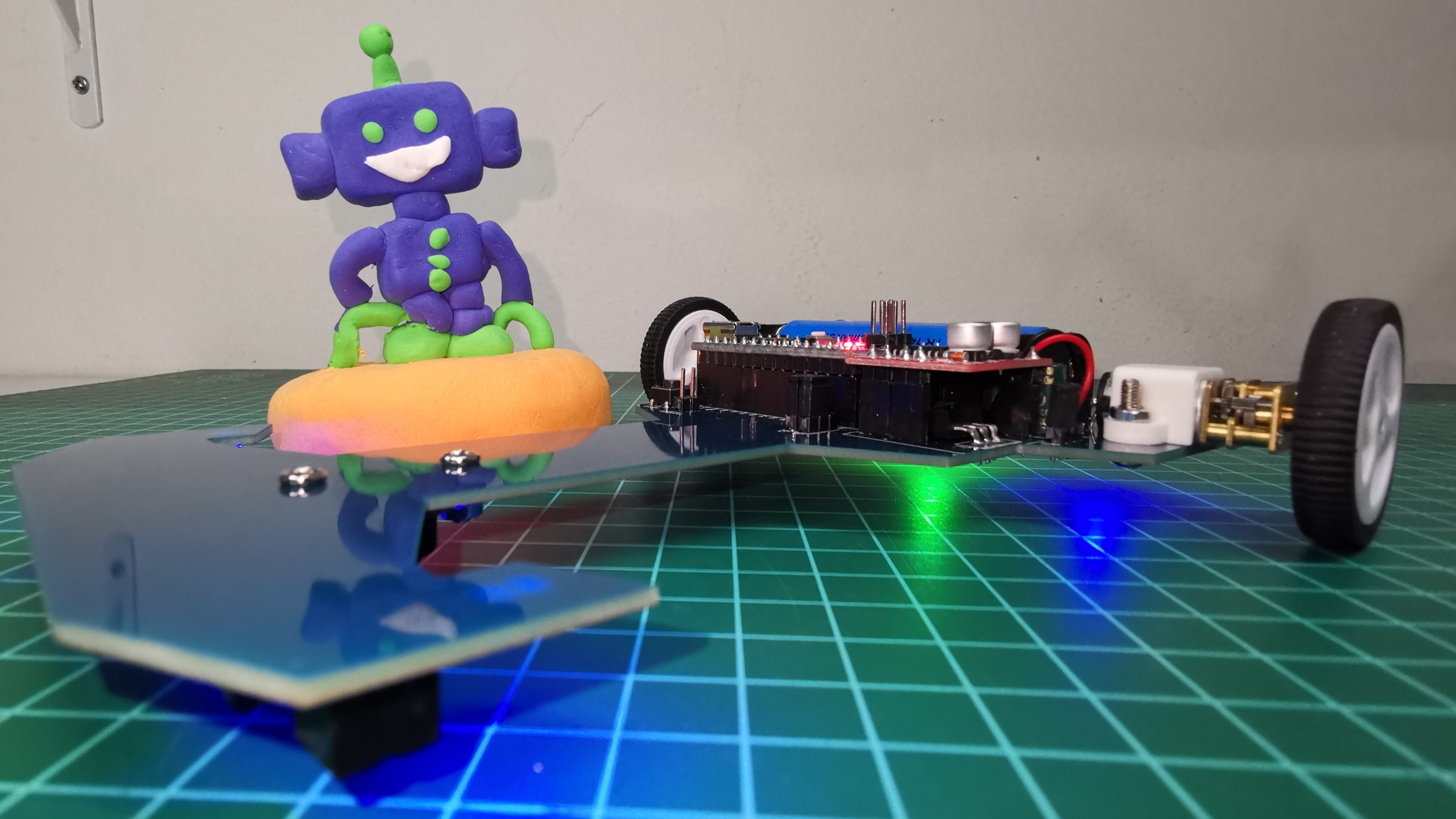
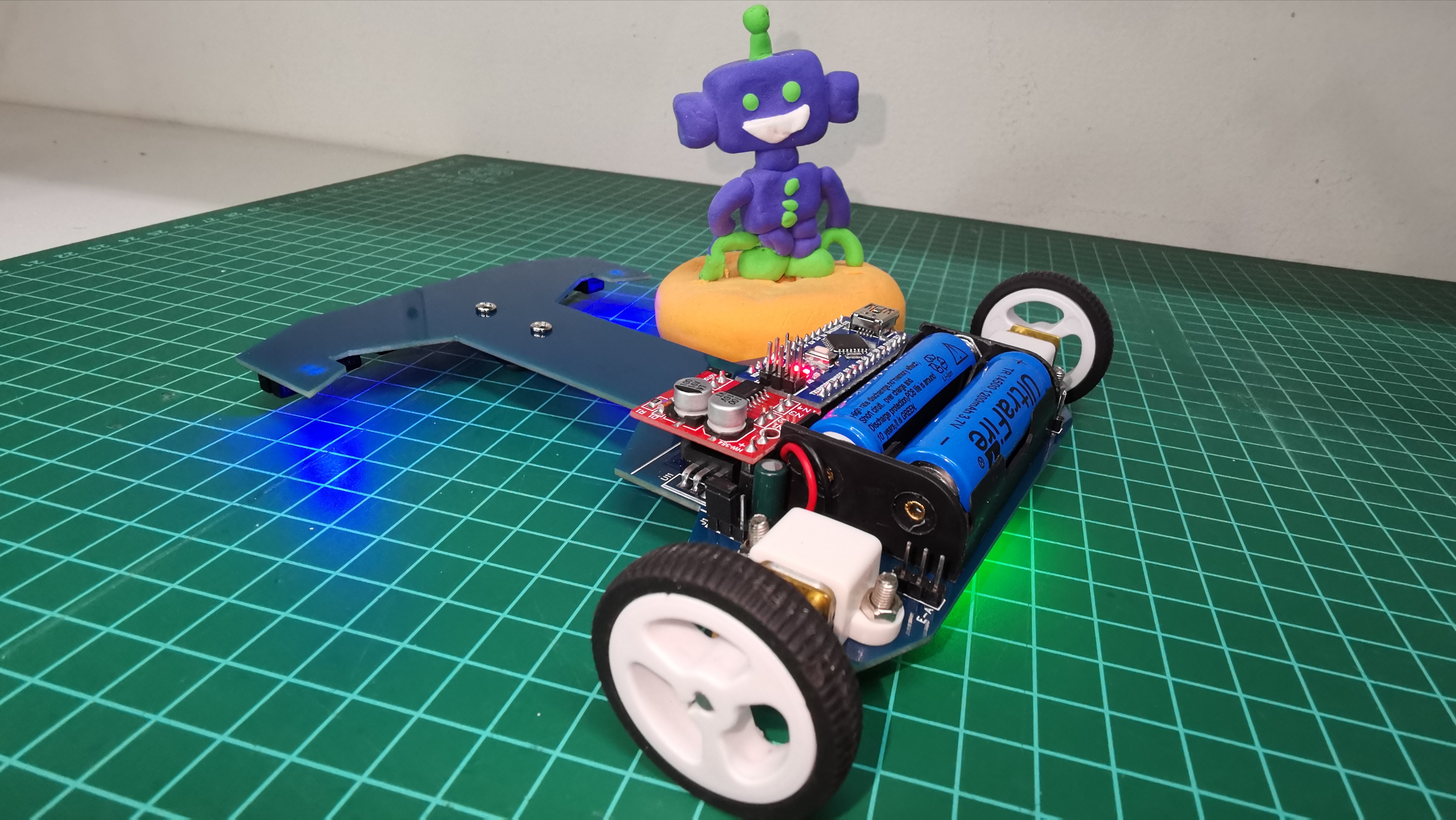
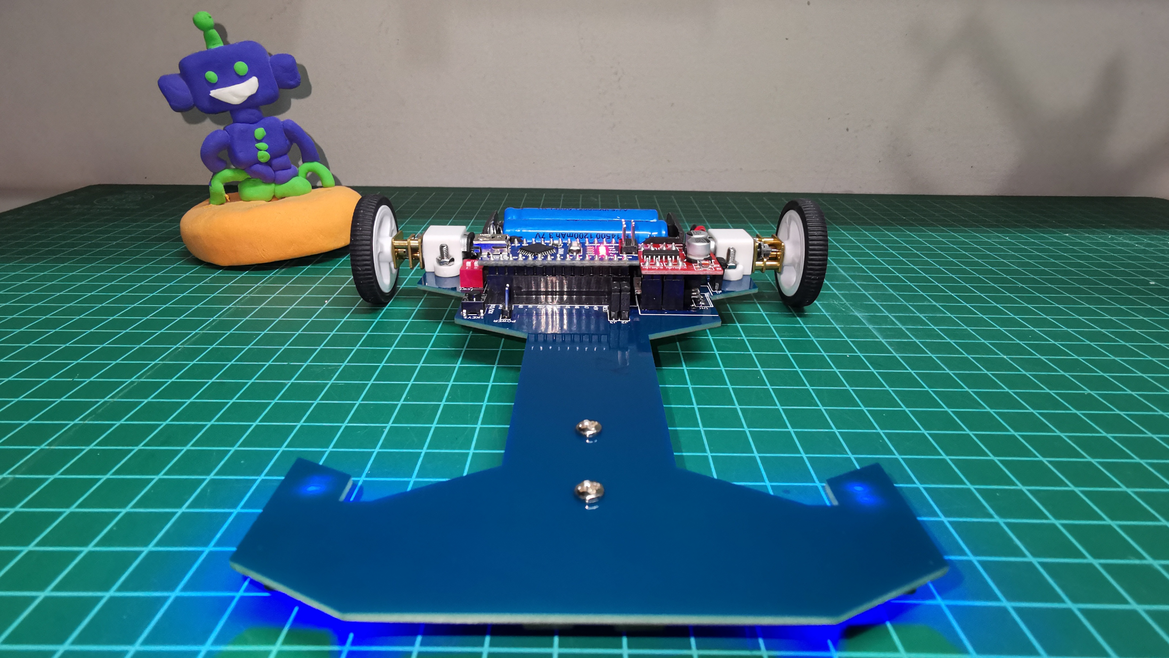
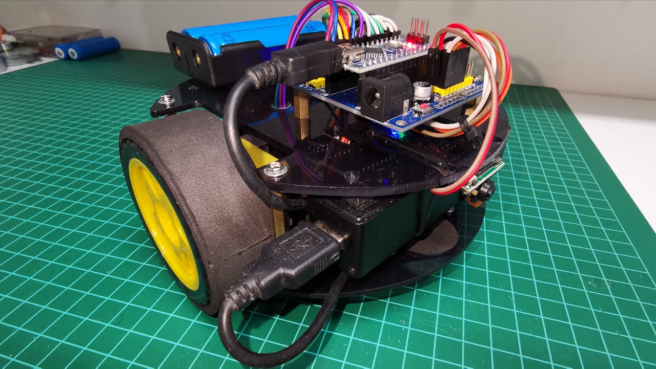
This is my second line follower robot (Version 4). Unlike the previous one, I have made the design of the printed circuit (Chassis).
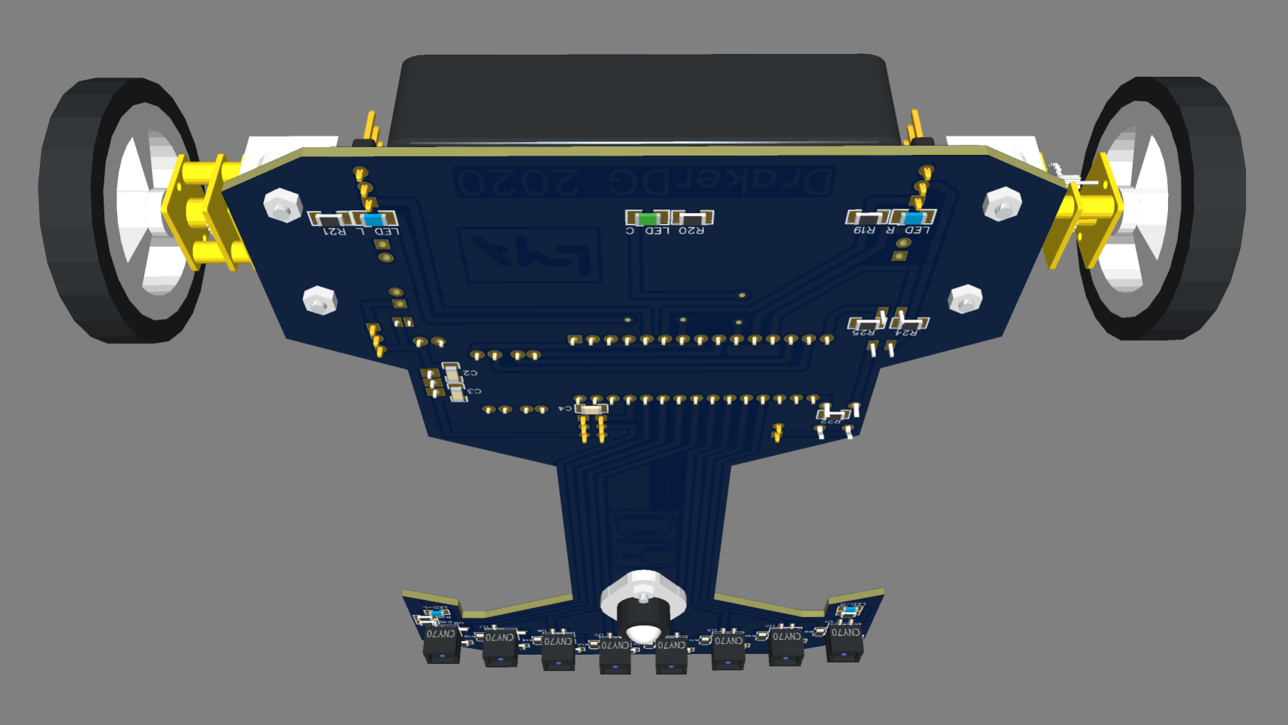
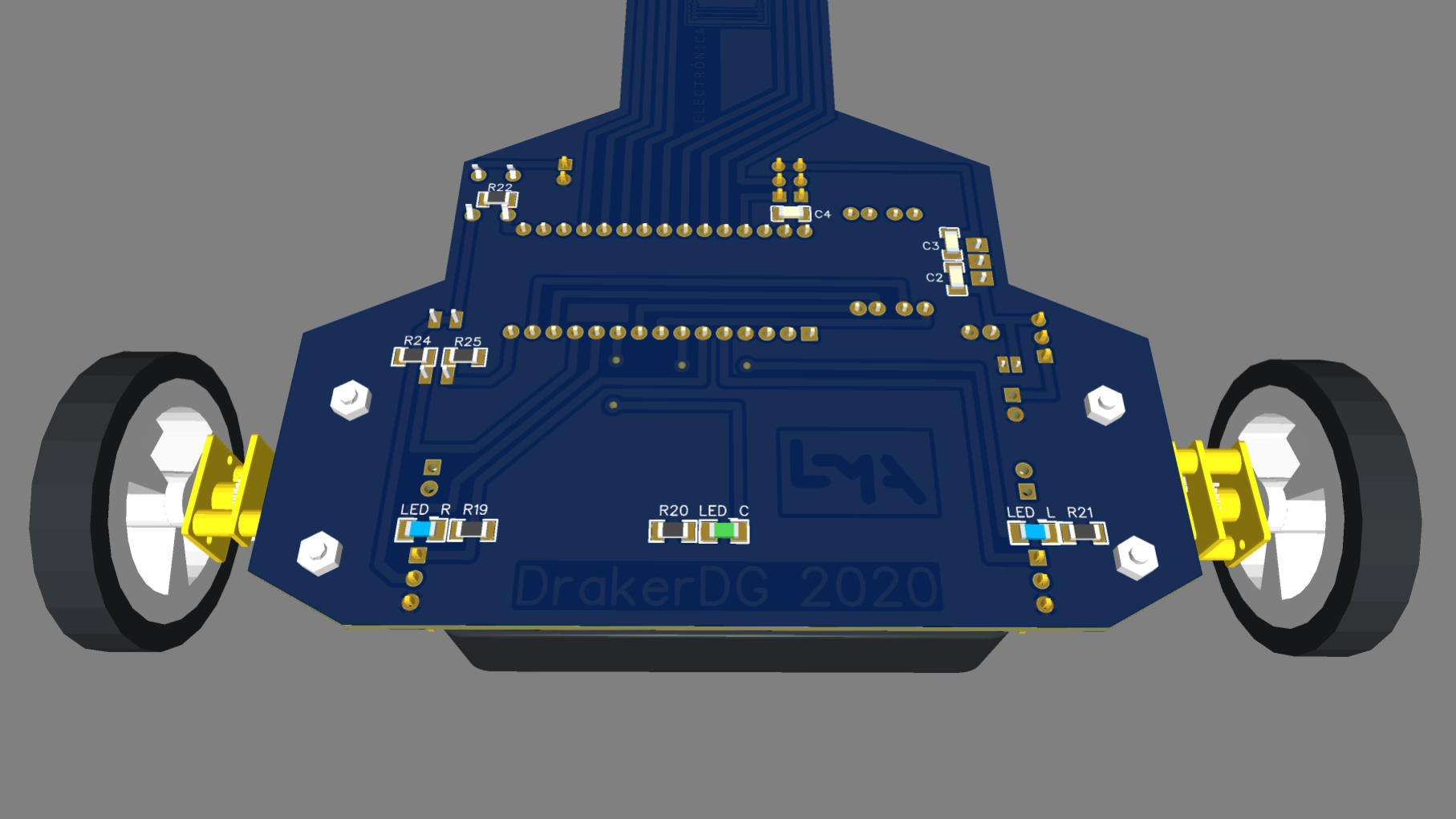
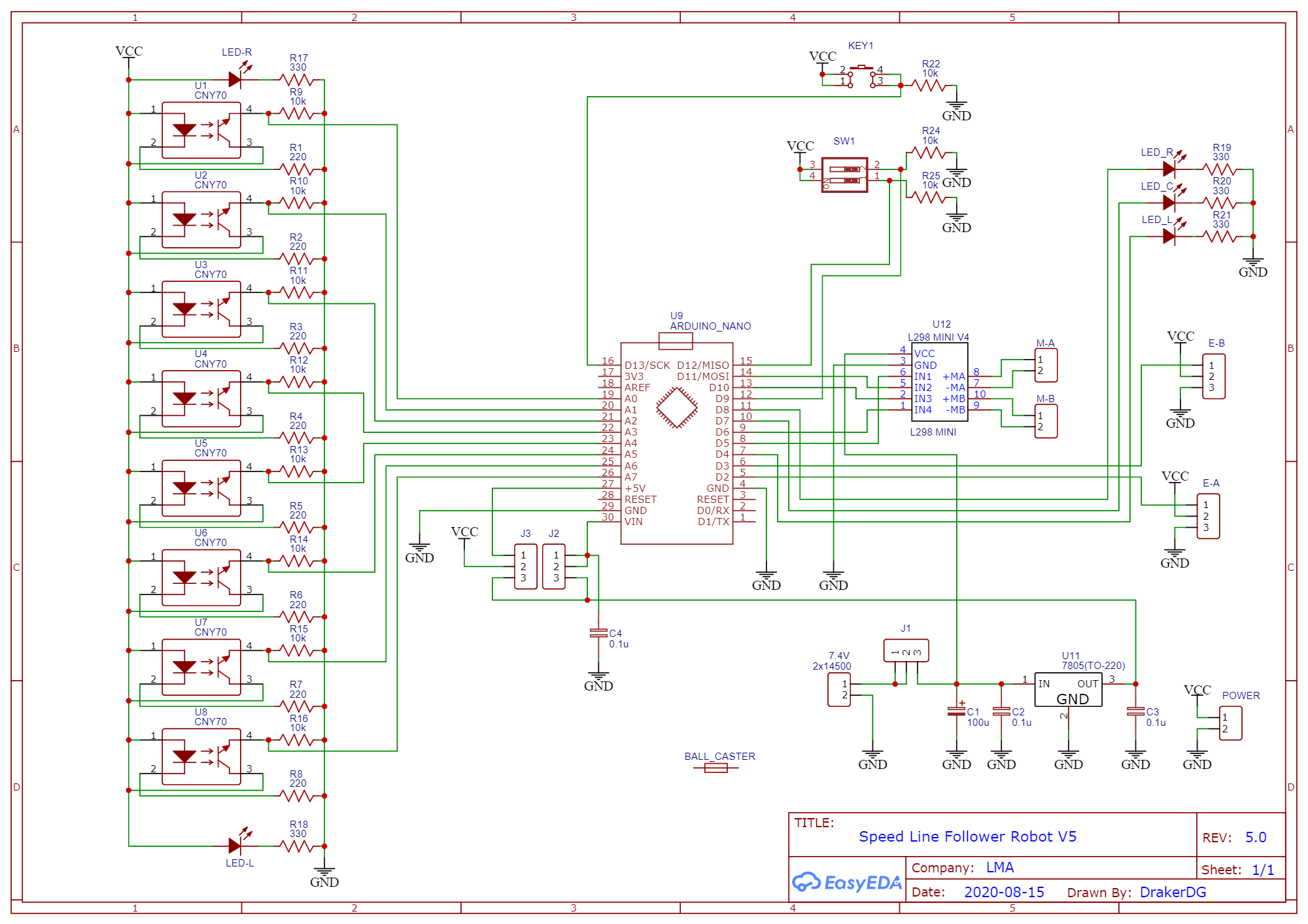
This is my second Line Follower Robot (Version 4). Unlike the previous one, I have made the design of the printed circuit using EasyEDA. This printed circuit acts as the chassis of the robot. The PCB manufacturing has been carried out by JLCPCB and I must say that they exceeded my expectations with impressive quality and shipment in record time.
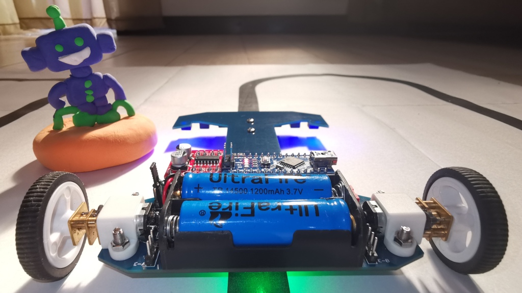
The following video shows the final result of the prototype in which I have included the 3D models designed in Tinkercad.
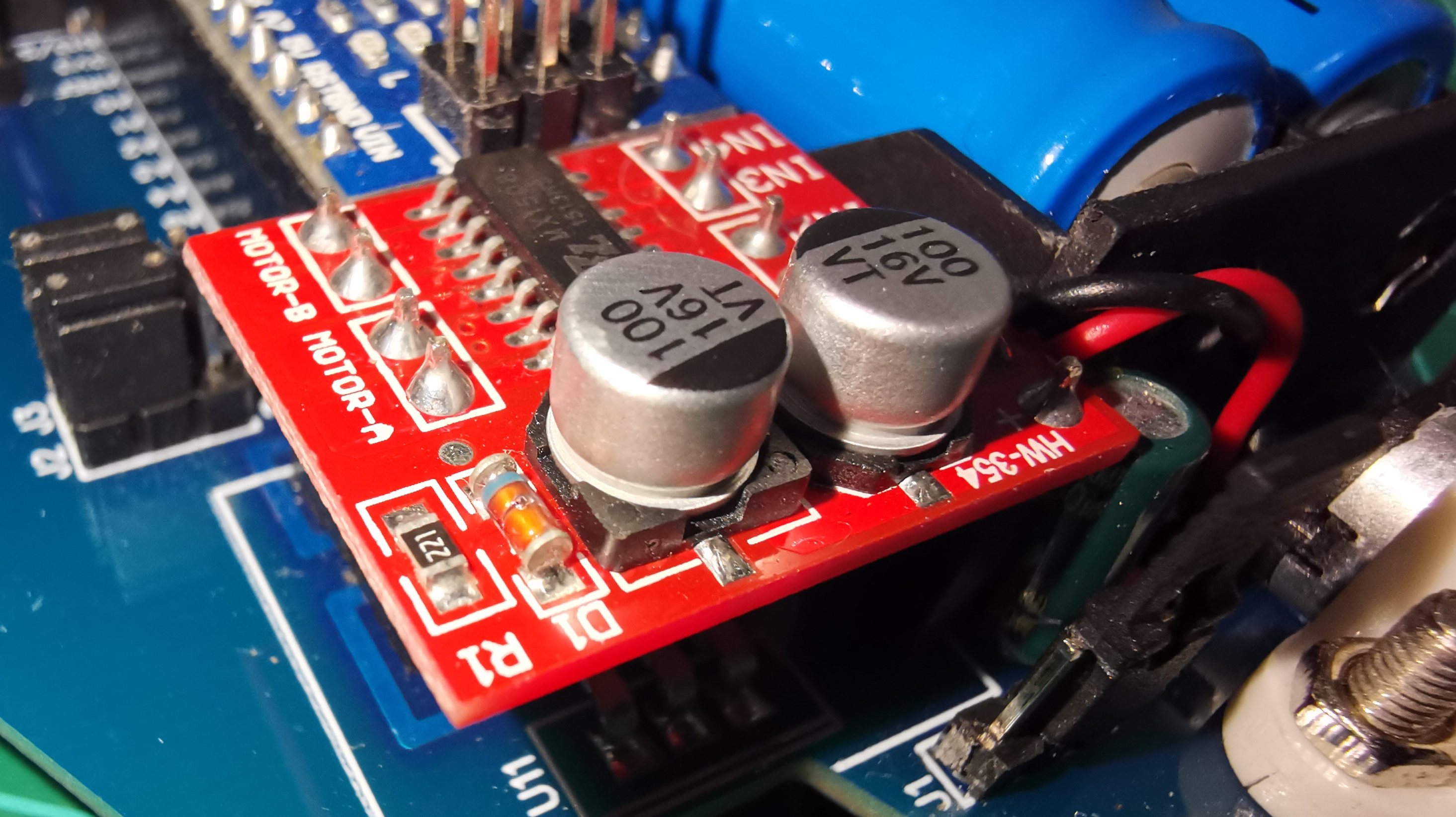
In the following video I show the tests carried out with the Mini Motor Driver (MX1508).
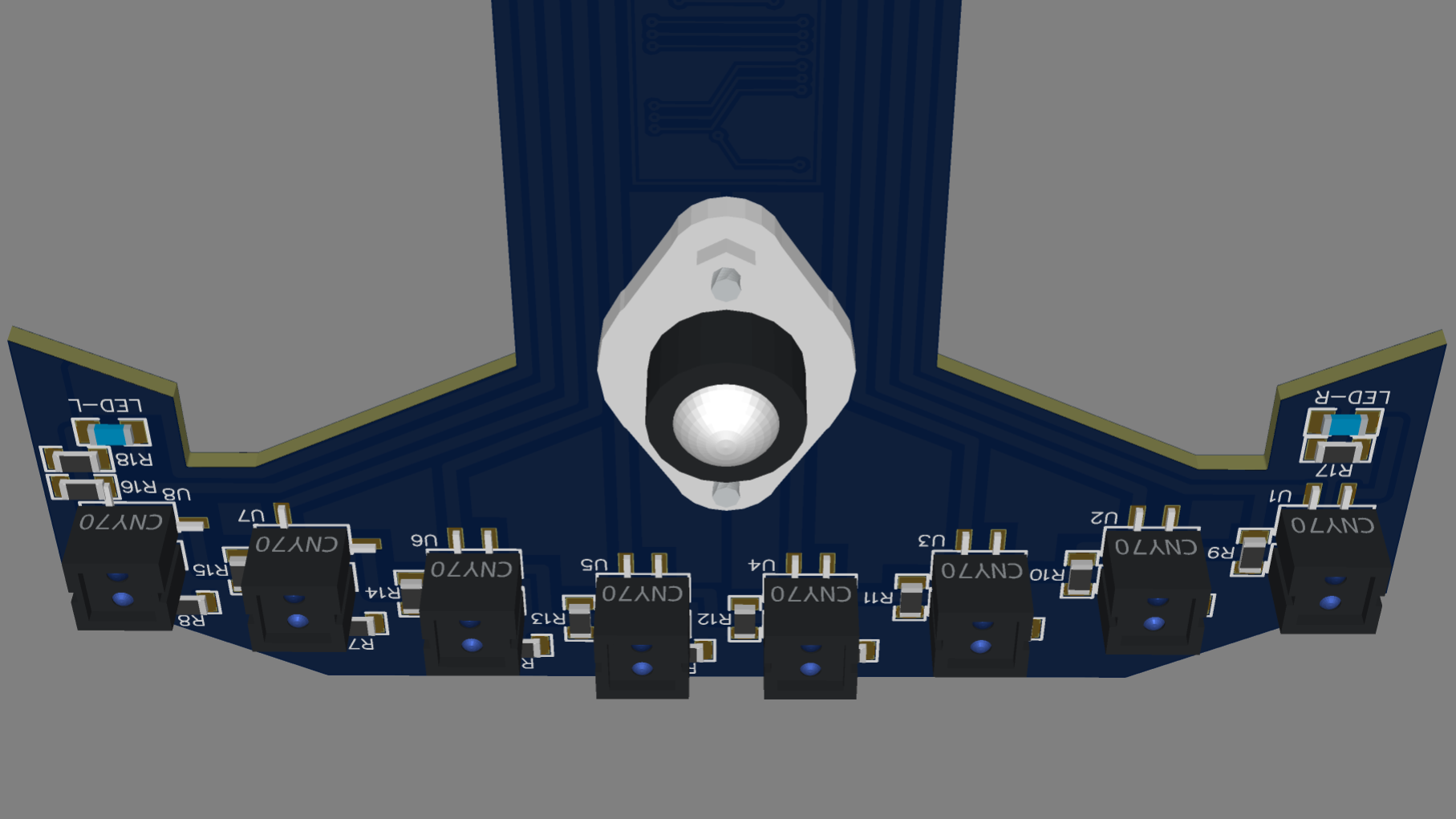
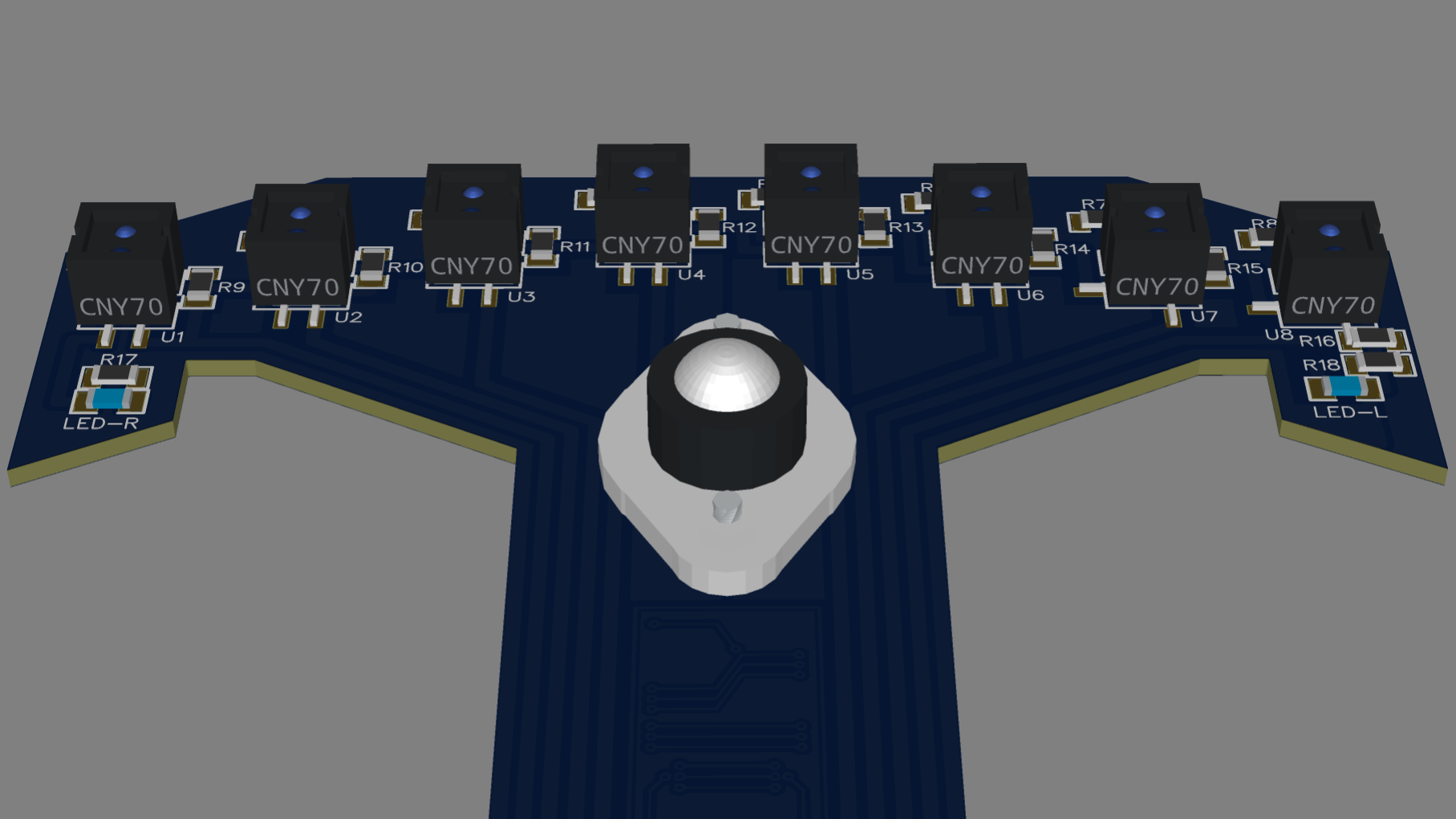
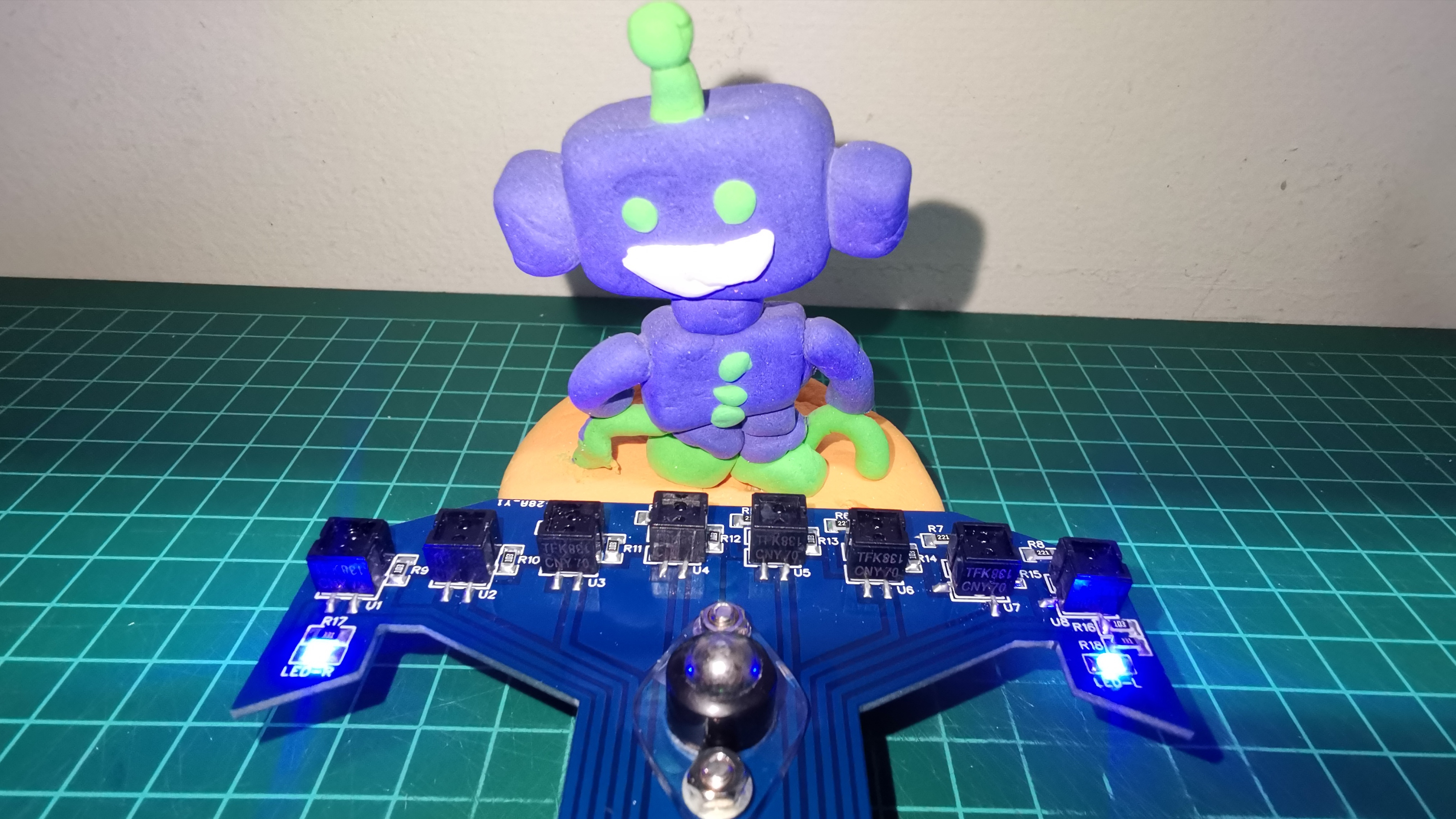
In the next video I show the tests with the 8 CNY70 sensors. These sensors are measured analogically, through ports A0 to A7 of the Arduino Nano. I use an initial algorithm to calibrate the sensors by normalizing the range from 0 to 1000, where 0 represents the white background and 1000 the black line. Upon completing the calibration, it enters the loop and starts the reading cycle, calculating the position from 0 to 7000, which represents the left sensor to the right sensor respectively. This position value is used to calculate the proportional error P. The range of P is -3500 (left) to 3500 (right), with 0 being the center value. The algorithm memorizes the value of the position of the last sensor (left or right) that detected the black line, this with the purpose of using this data for braking actions and line recovery.
The final test with the circuit 95% mounted, is shown in the following video. A last amperage test having a maximum consumption of 200mA.
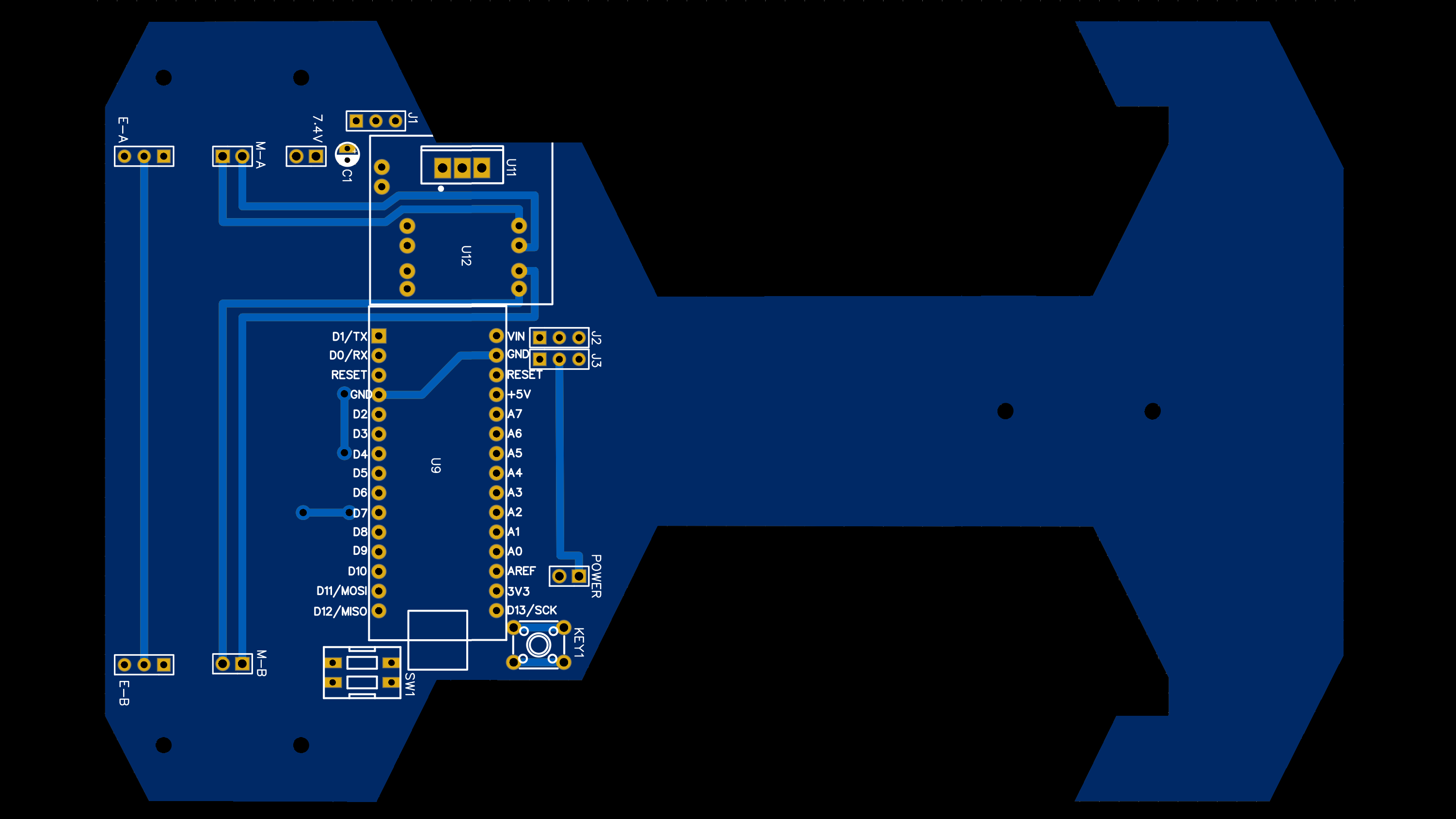
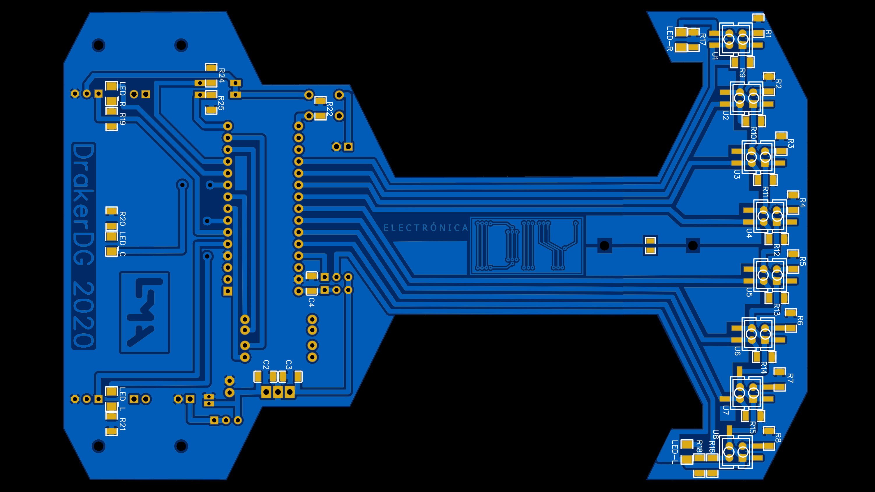
This is the latest version of the robot’s printed circuit, ready to be manufactured on JLCPCB.
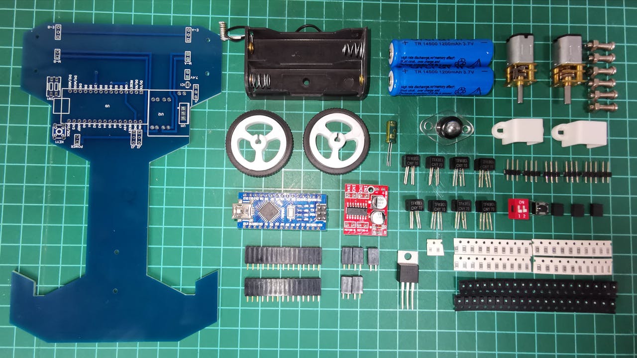
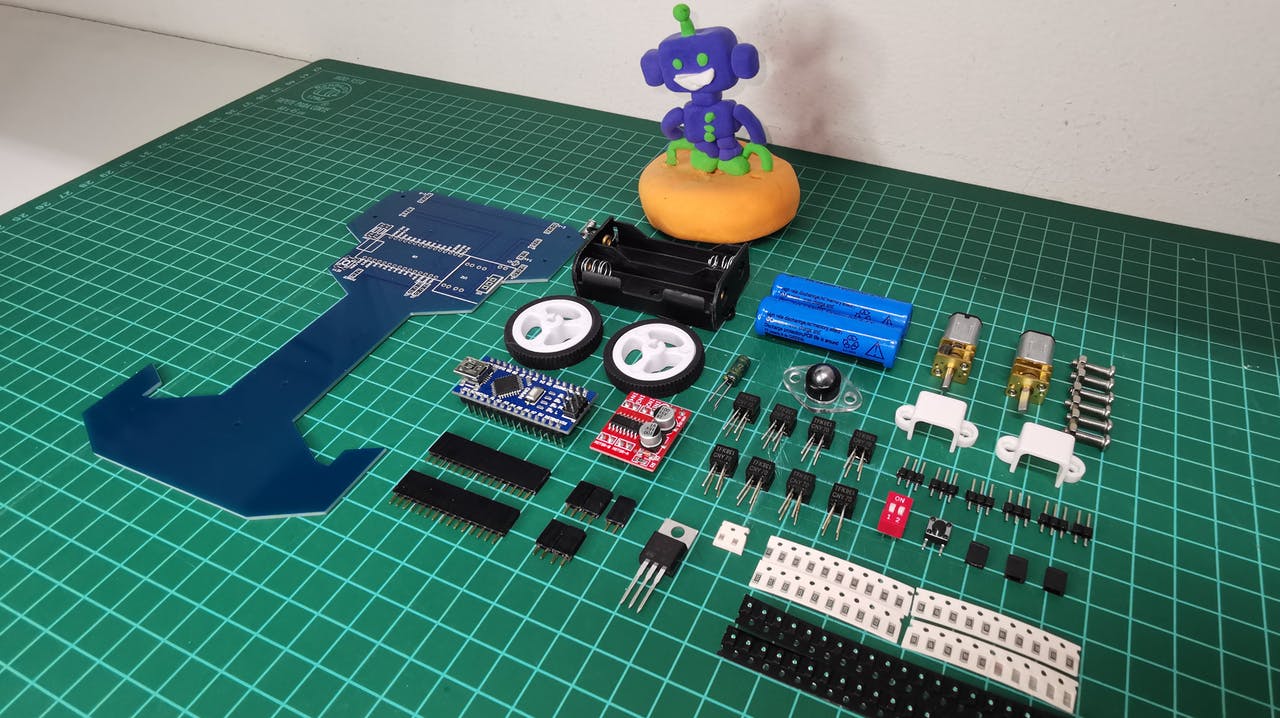
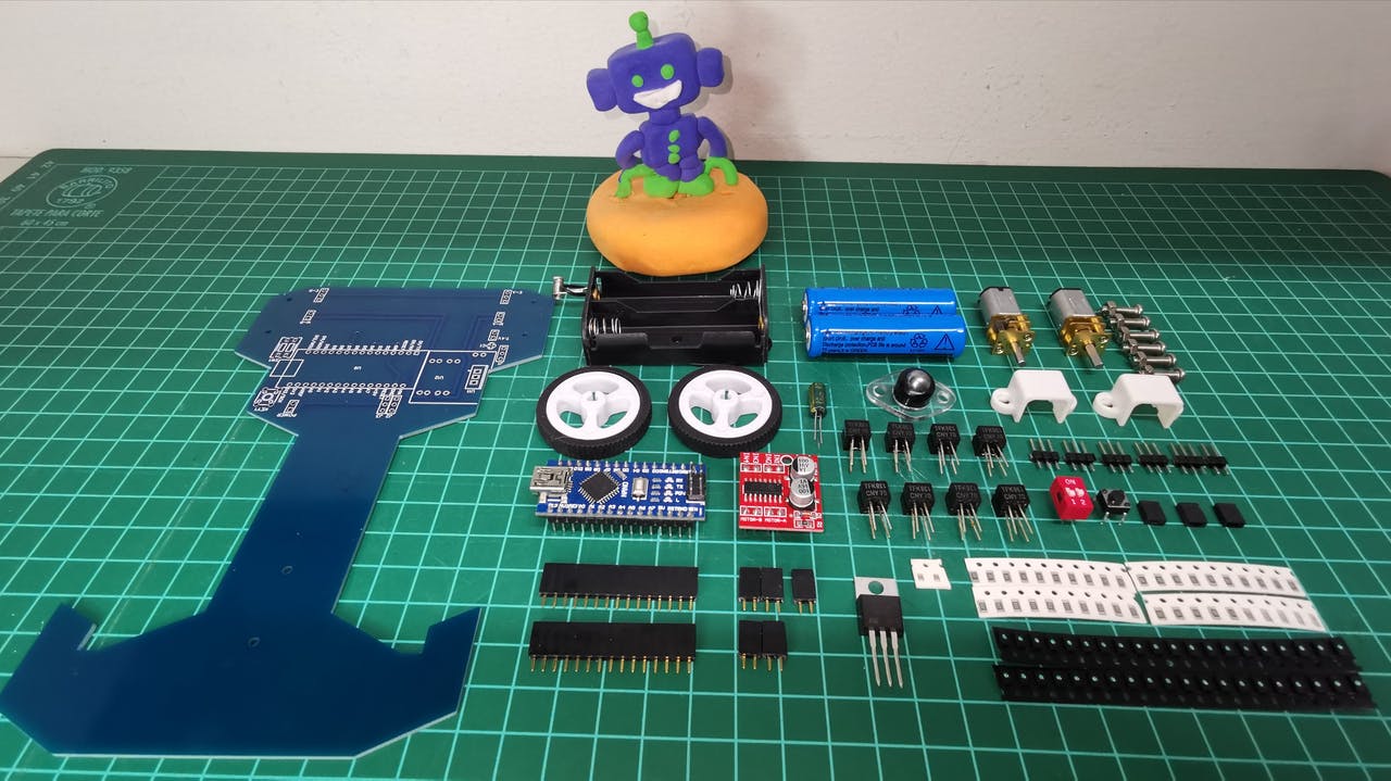
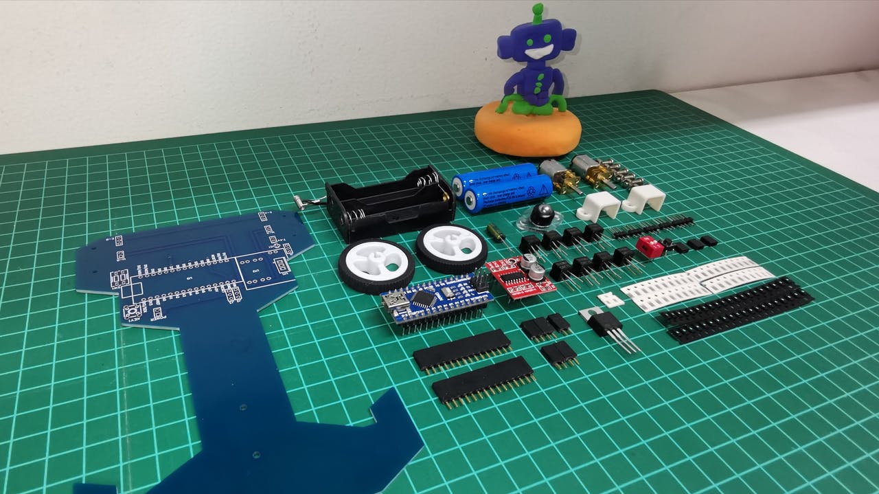
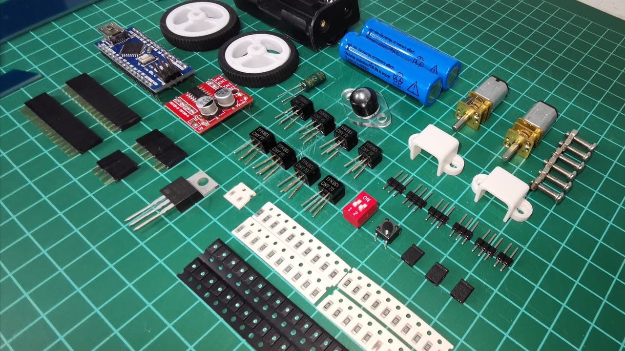
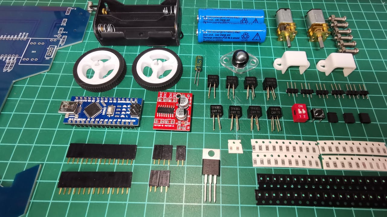
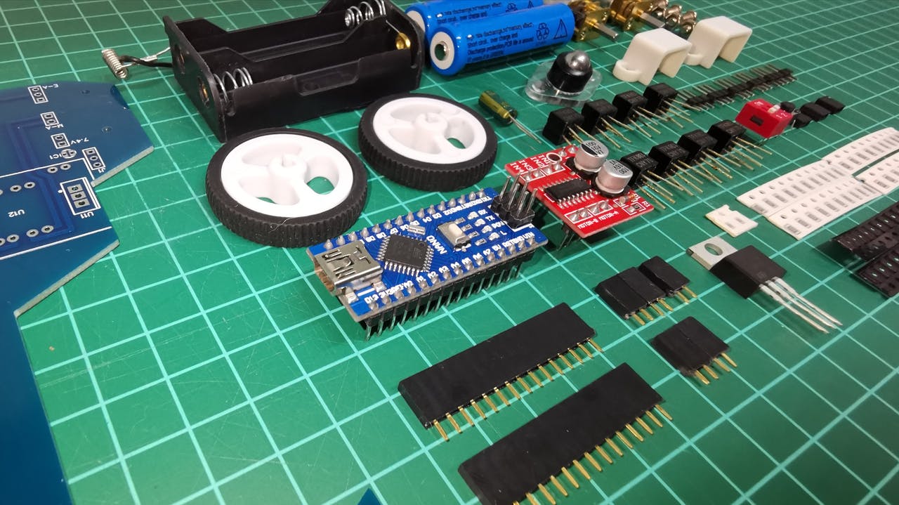
This is the unboxing.
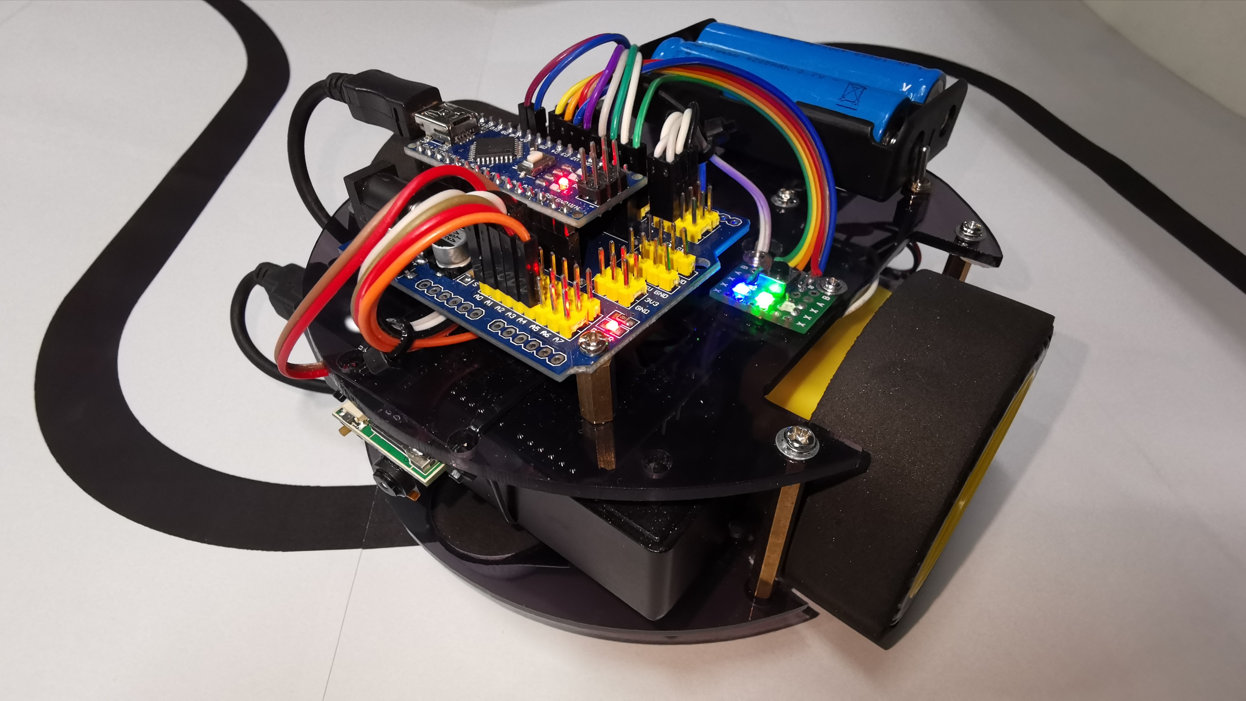
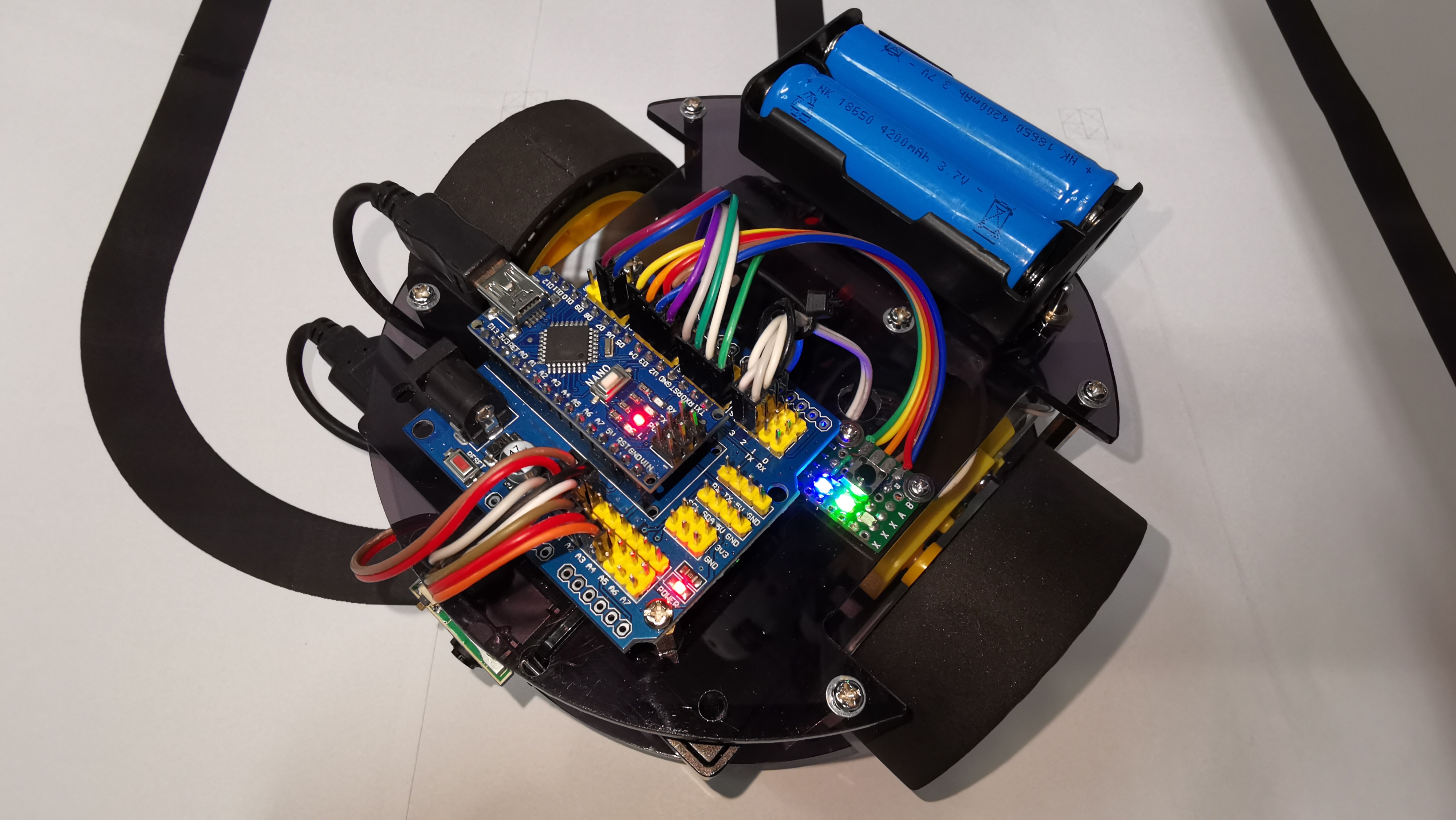
In the final stretch and already with the total of pieces, I show the assembly of my first Speed Follower Robot.
Finally and with a lot of effort I already have the fully built prototype, I show below how to load the code (Code Load Mode), how you can test the sensors and of course the tests on the track. Very happy with the operation, the test code manages to control the code very well. I have used a PID (Full) algorithm to smooth the corrections and regain the course of the line. Since everything can be improved, I will continue to play with the code to achieve a more efficient version.
hdrpl
hdrpl
hdrpl
hdrpl
qrf
hdrpl
hdrpl
hdrpl
hdrpl
oznorWO
qrf
qrf
hdrpl
hdrpl
hdrpl
hdrpl
hdrpl
hdrpl
hdrpl
hdrpl
hdrpl
hdrpl
hdrpl
oznorCO
hdrpl
hdrpl
hdrpl
hdrpl
hdrpl
hdrpl
hdrpl
hdrpl
hdrpl
hdrpl
hdrpl
As a complement, I did the simulation of this robot in the Webots application. It is still in the process of improvement but I share this video so that you can appreciate a way to perform mechanical and logical tests (Code) to control a robot in a virtual environment and that helps to understand the operation of a physically built robot.
I present to you the advance of the robot following lines that I have worked lately.
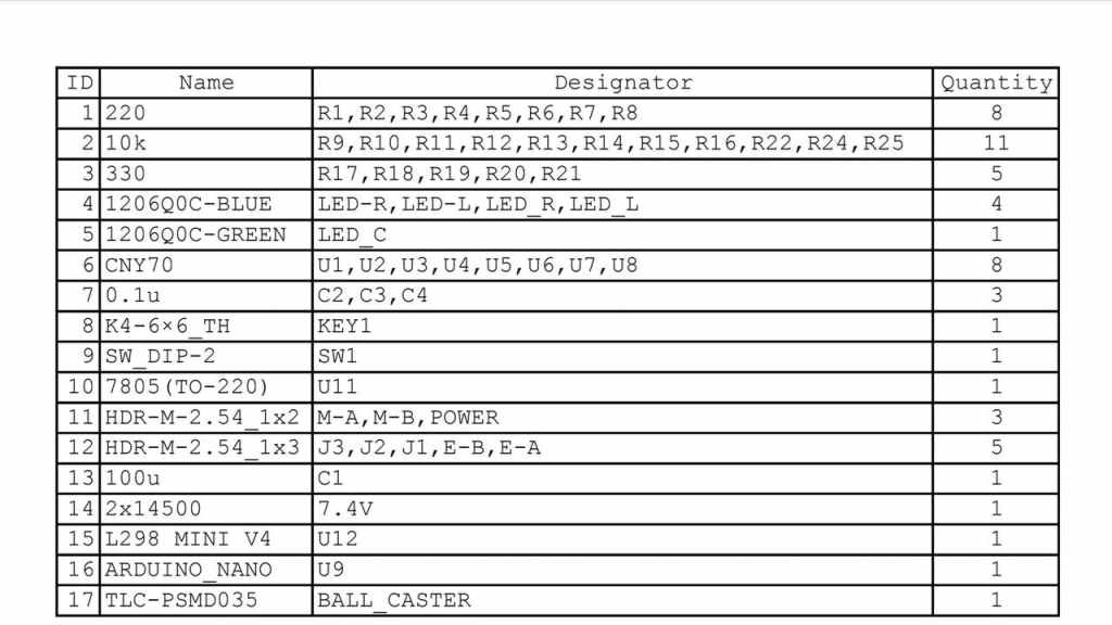
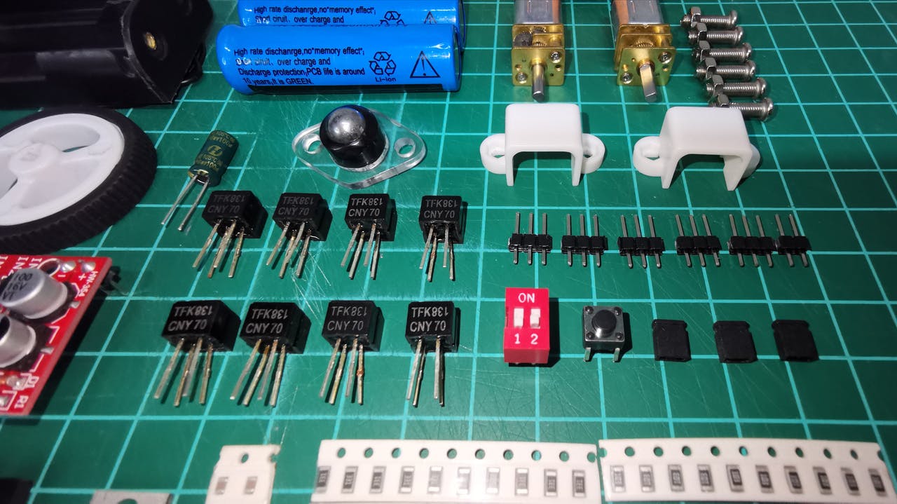
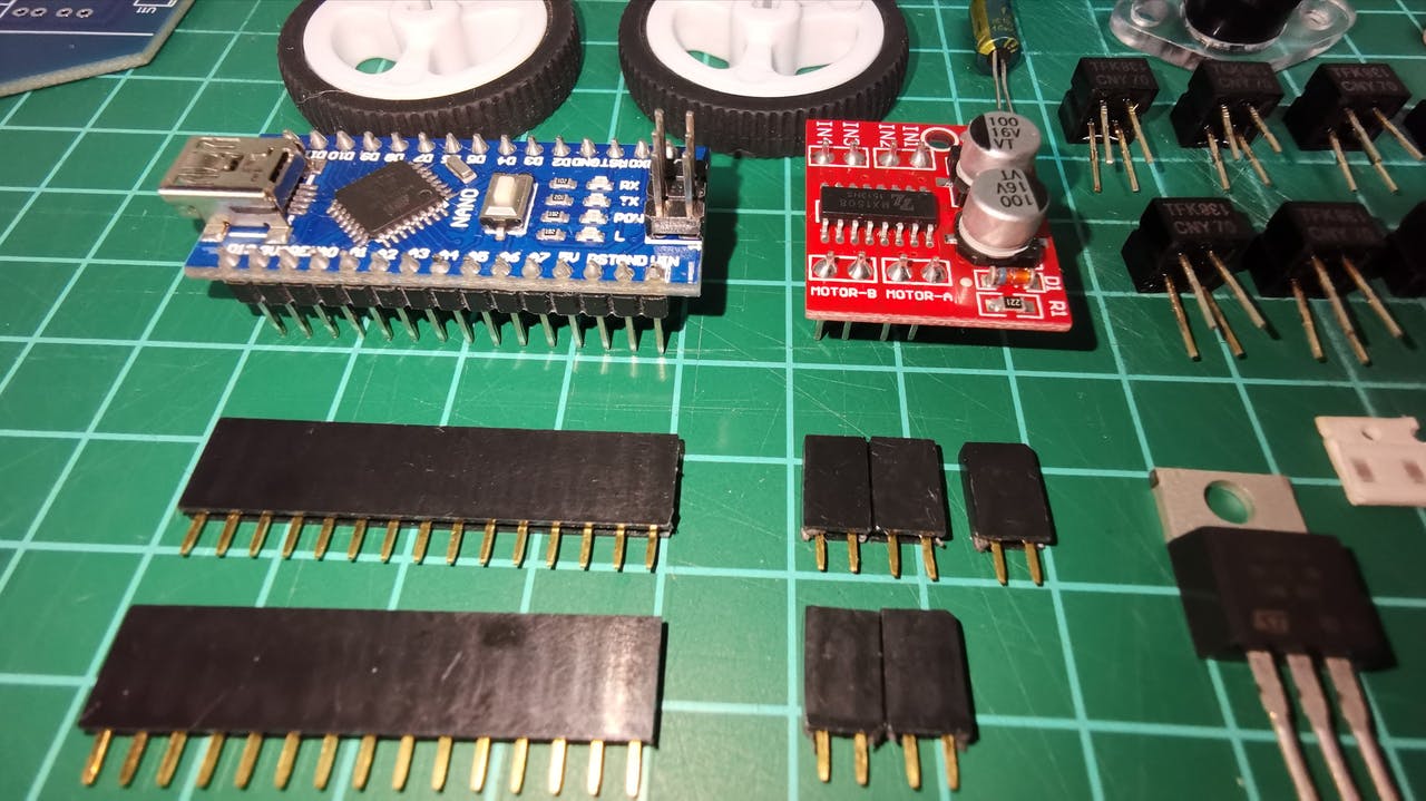
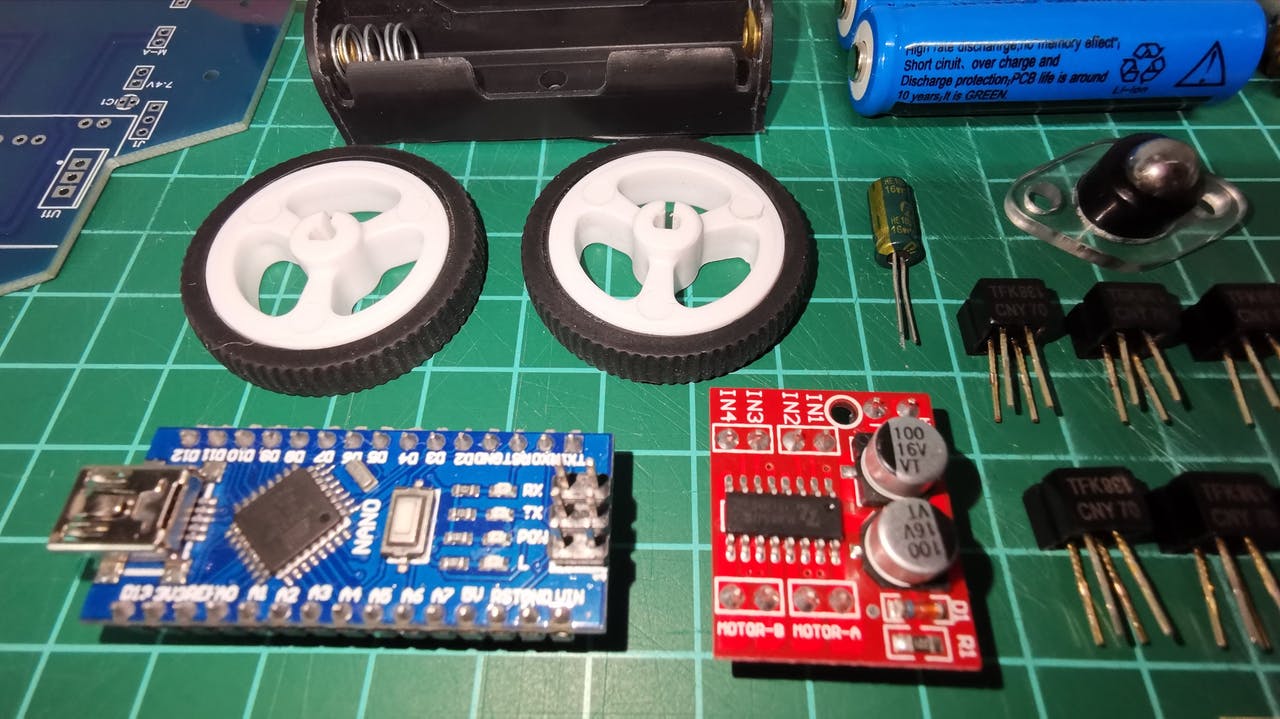
Components:
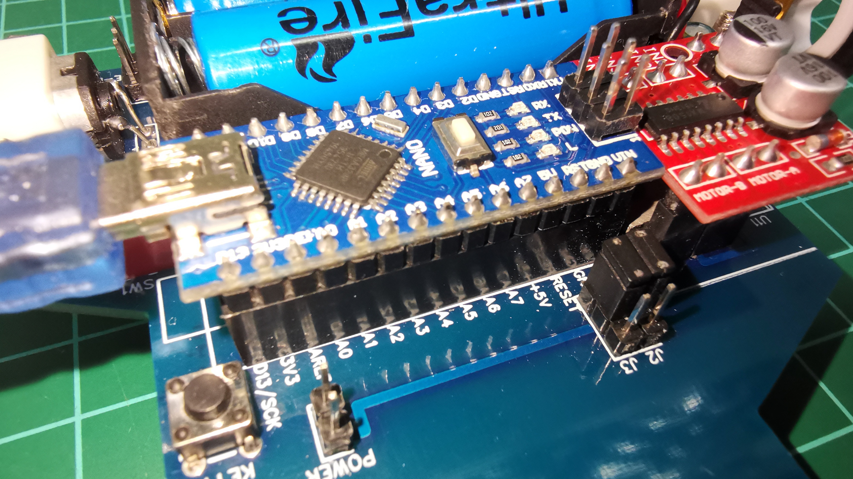
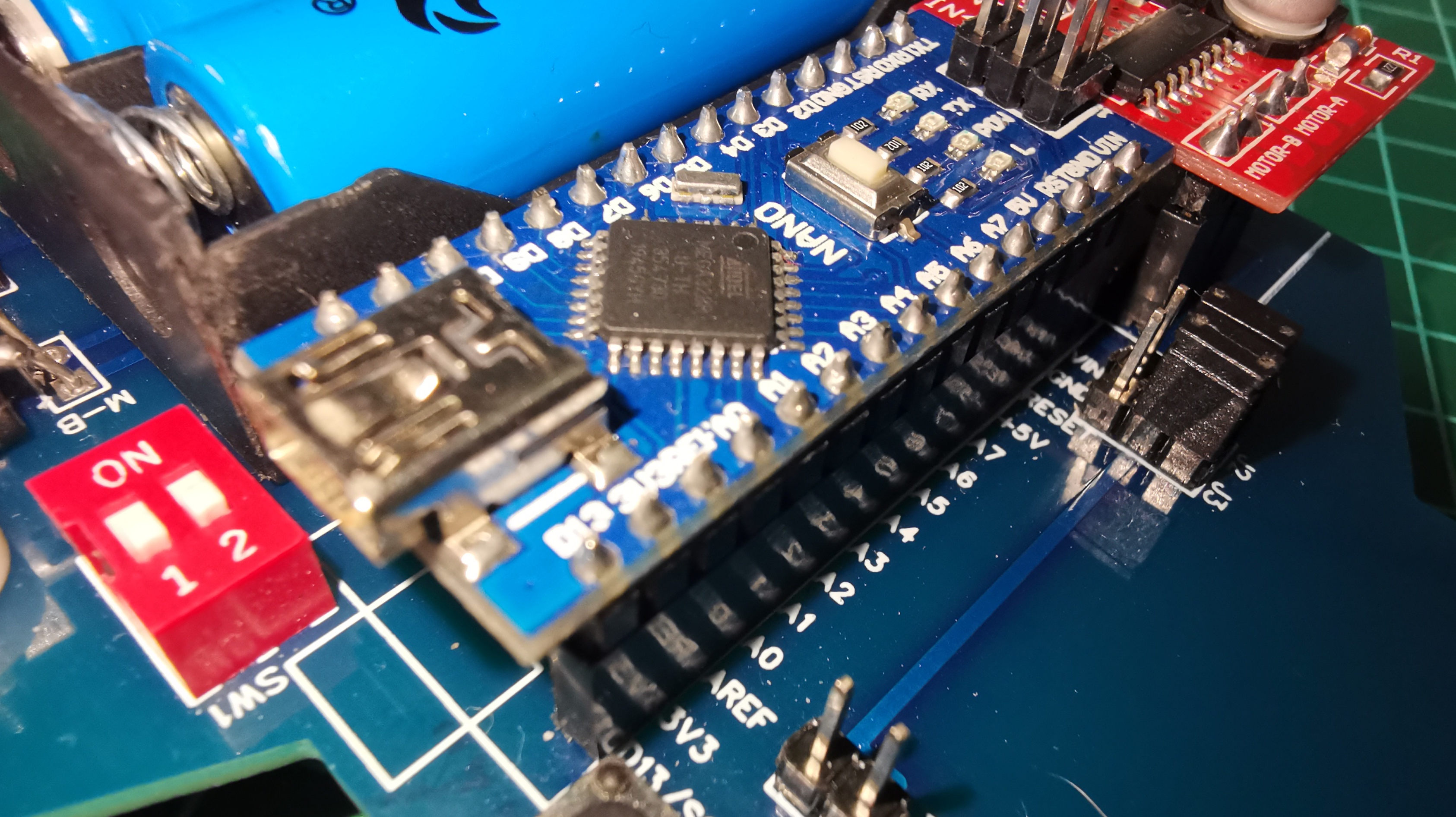
1 Arduino Nano
1 Arduino Nano Shield
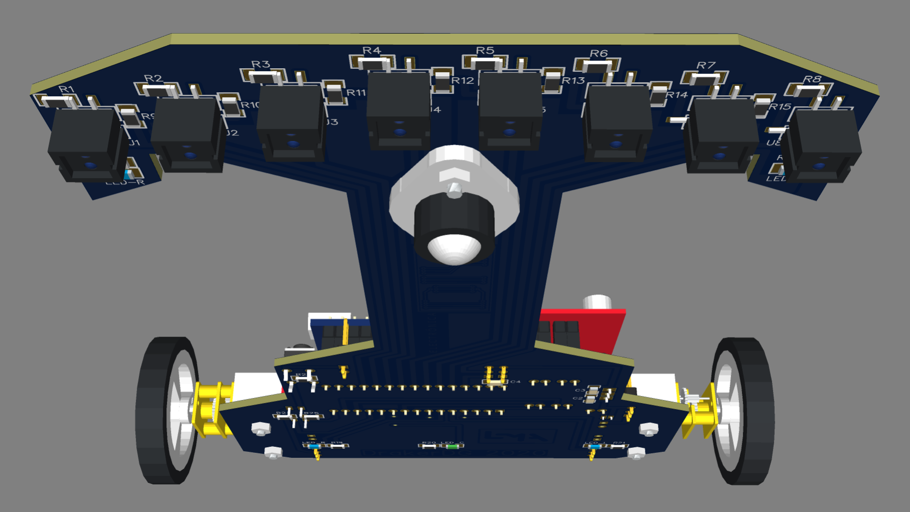
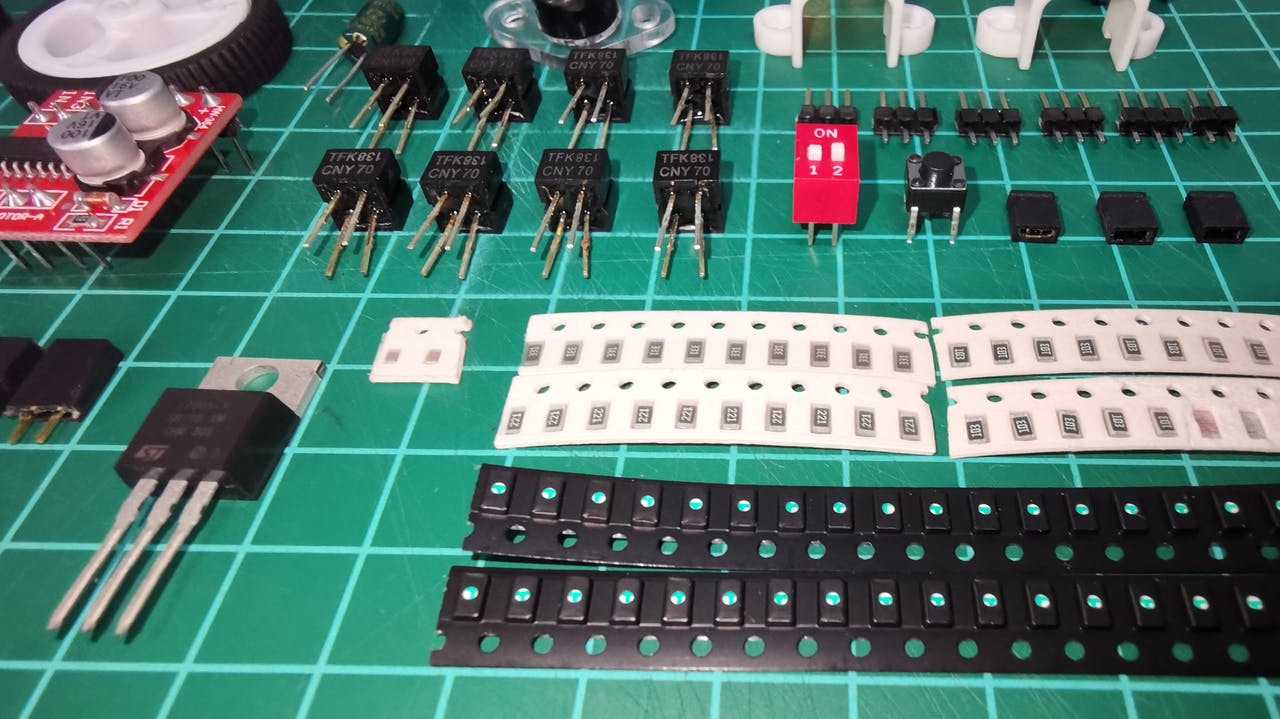
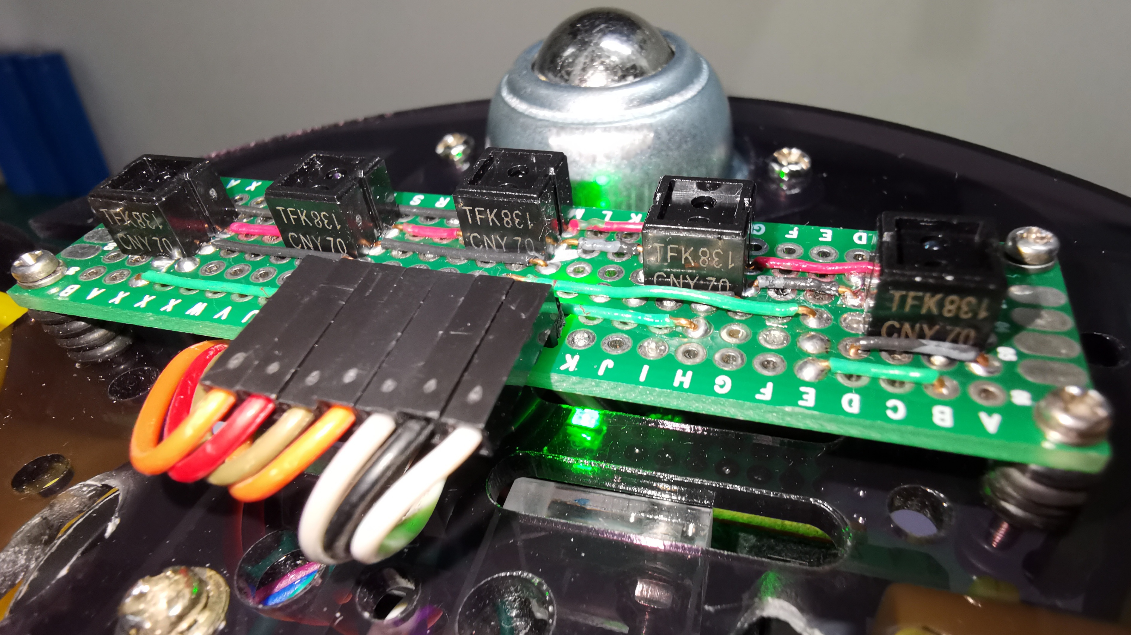
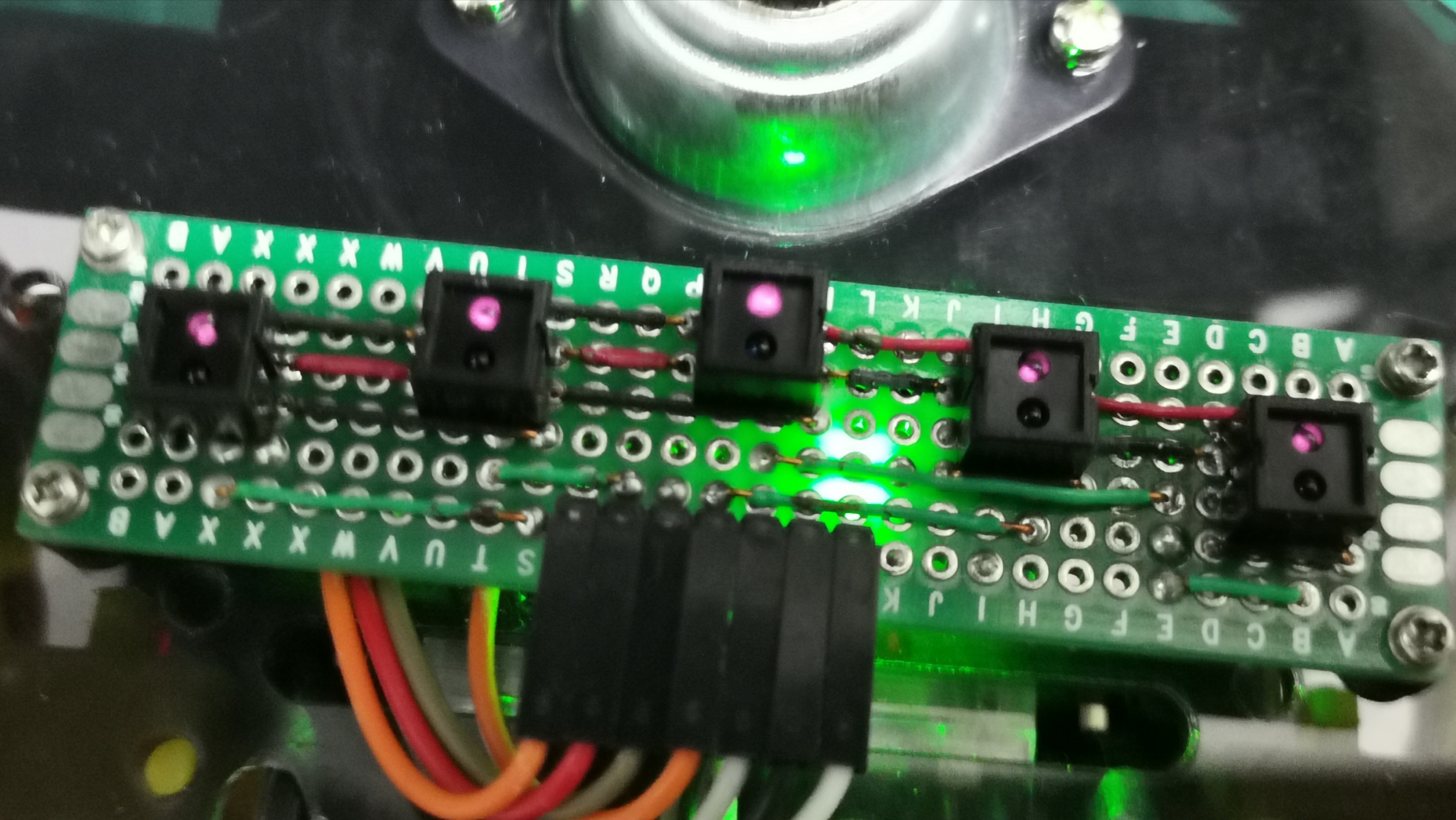
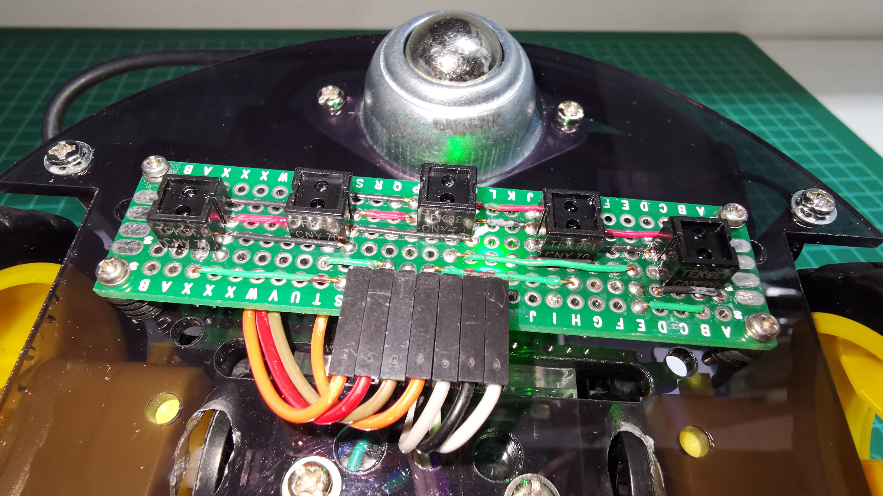
5 CNY70 sensors
2 IR Sensors GP1A01 (Similar FC-03)
1 Driver L298N
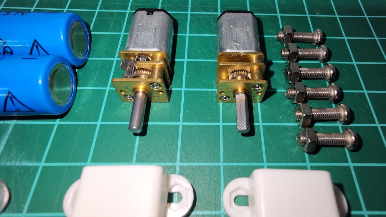
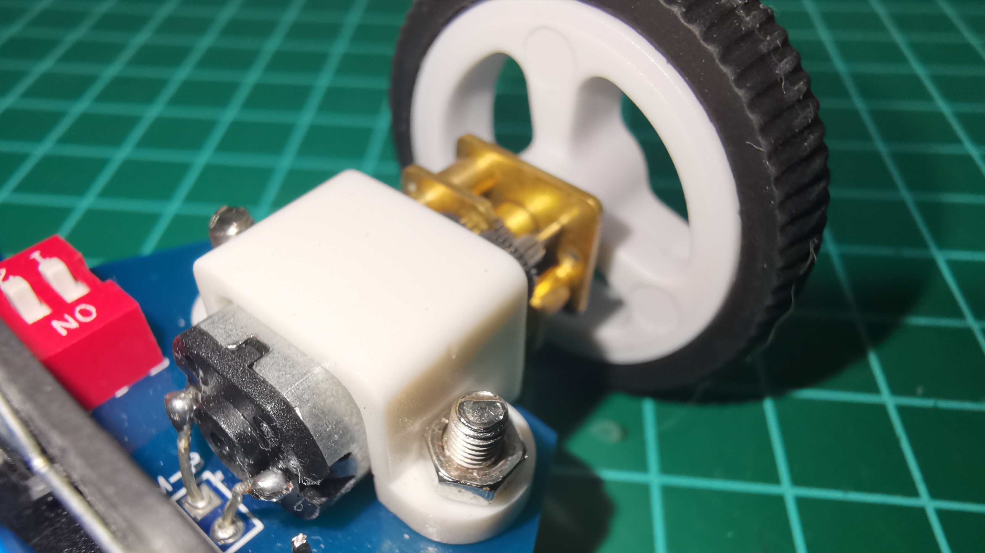
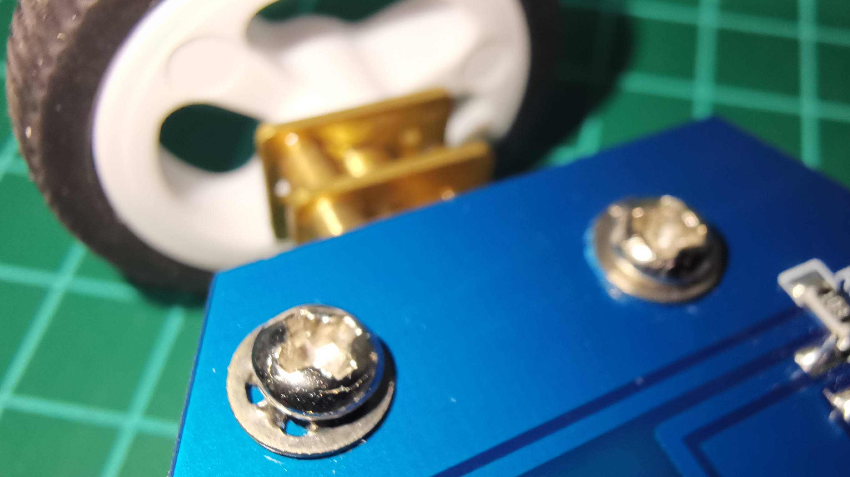
2 Motors with gearbox and encoder
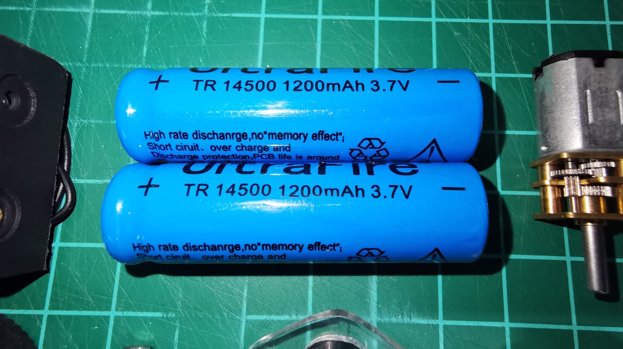
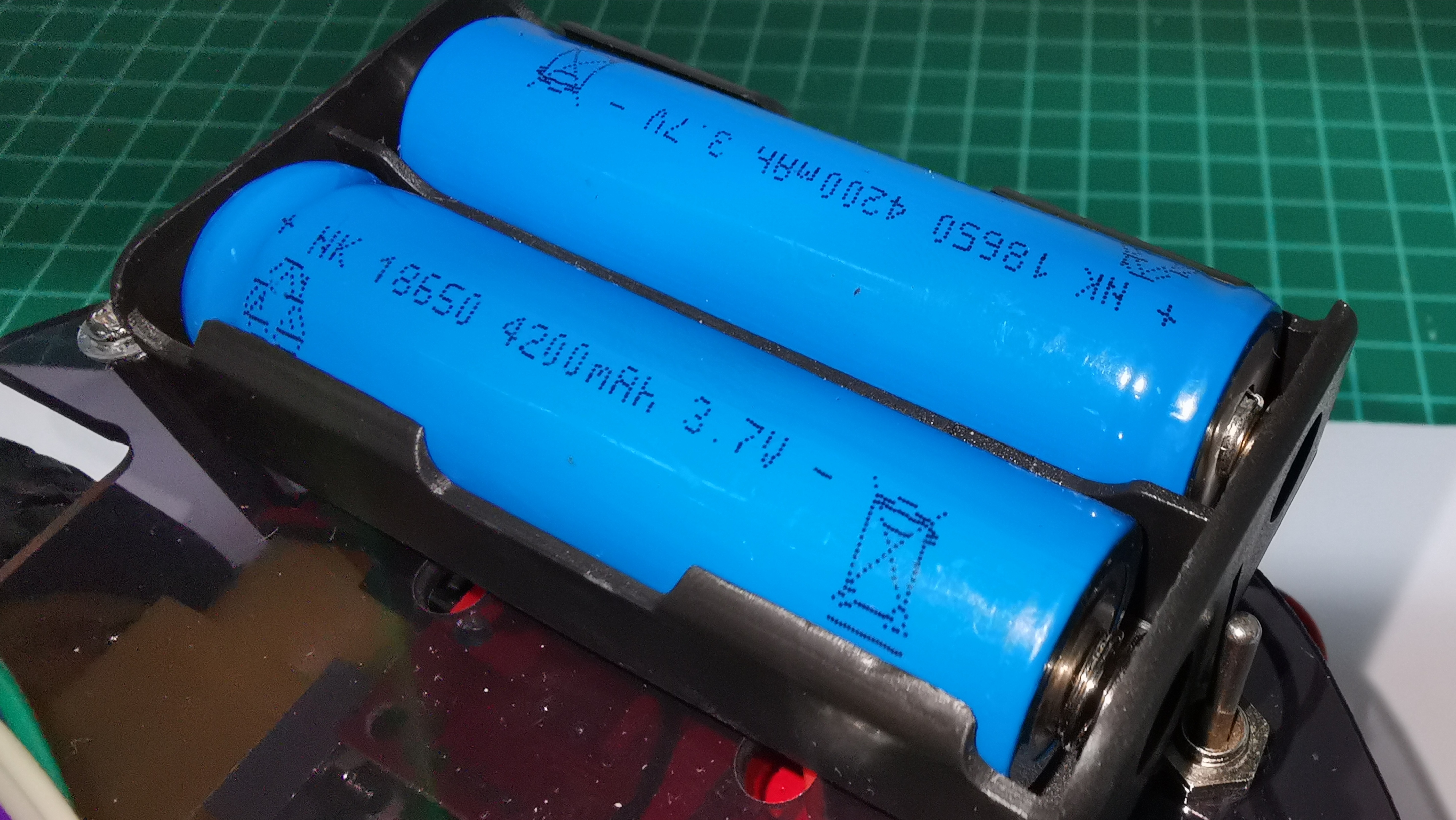
2 Batteries 3.7V 4200mAH 18650
1 18650 battery holder
1 5V USB charger
1 1P1T switch 1 Pushbutton
1 2-tier circular acrylic chassis
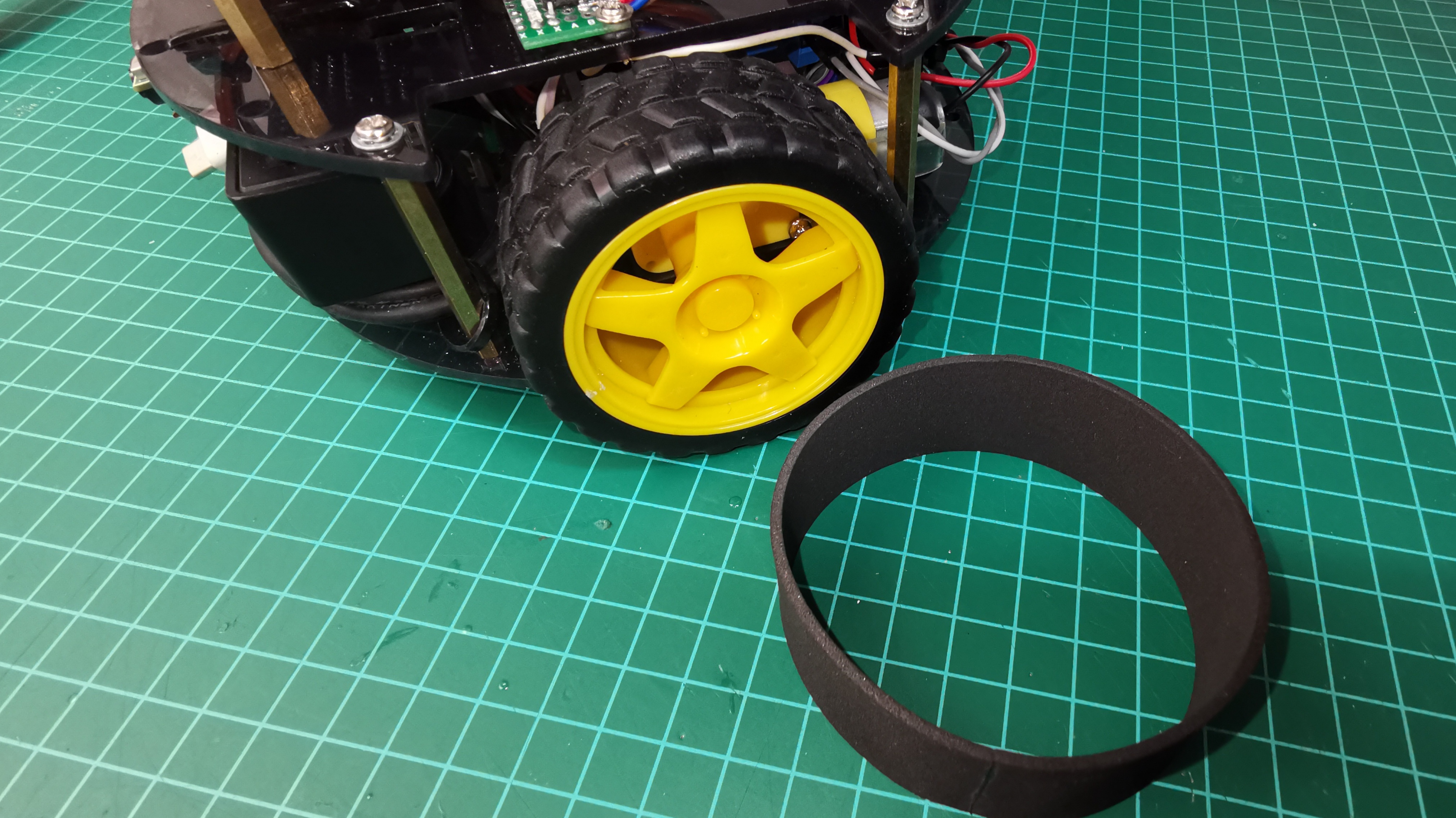
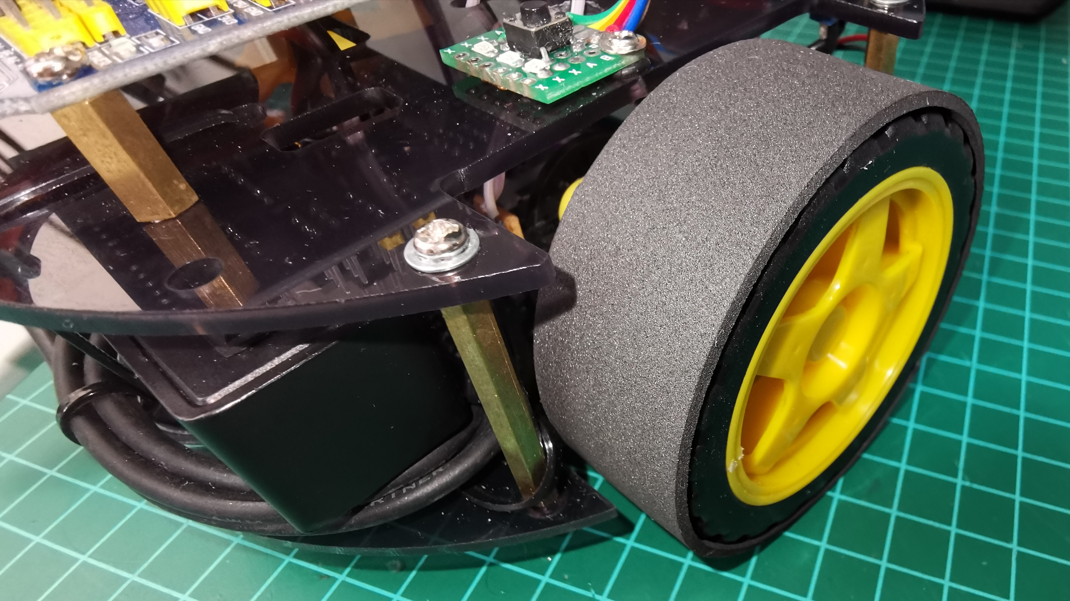
2 Wheels covered with eva foam
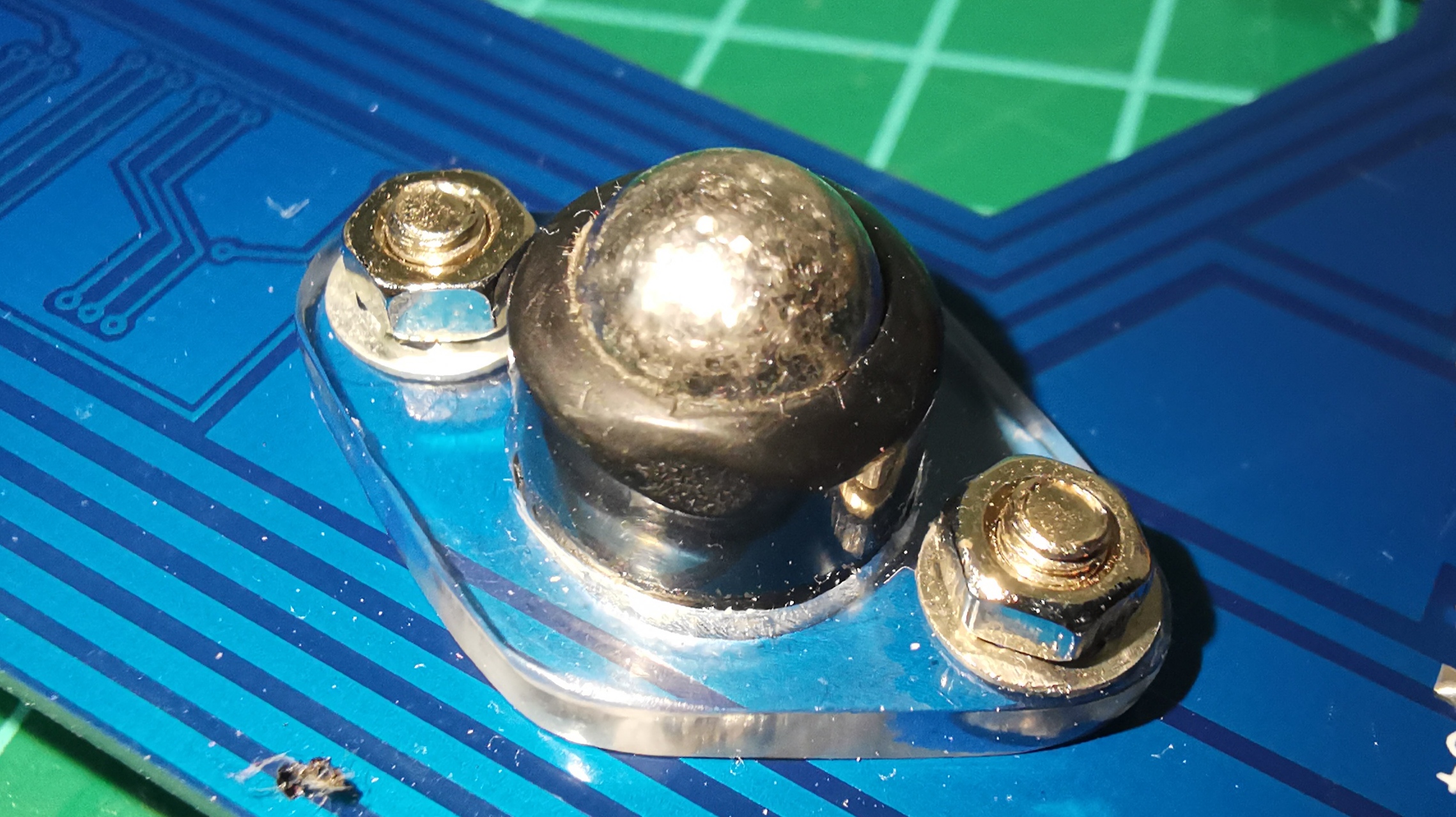
2 Sphere wheels
2 double-sided perforated breadboard
Some LEDs and SMD resistors and various connecting cables
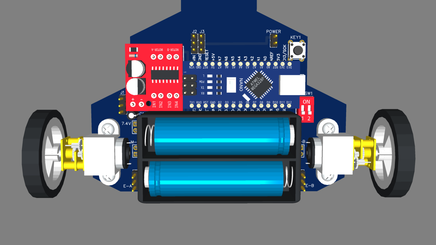
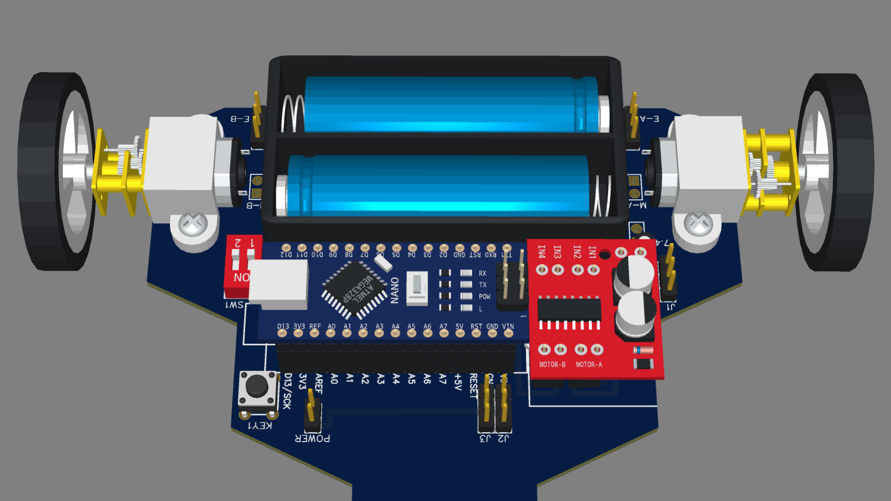
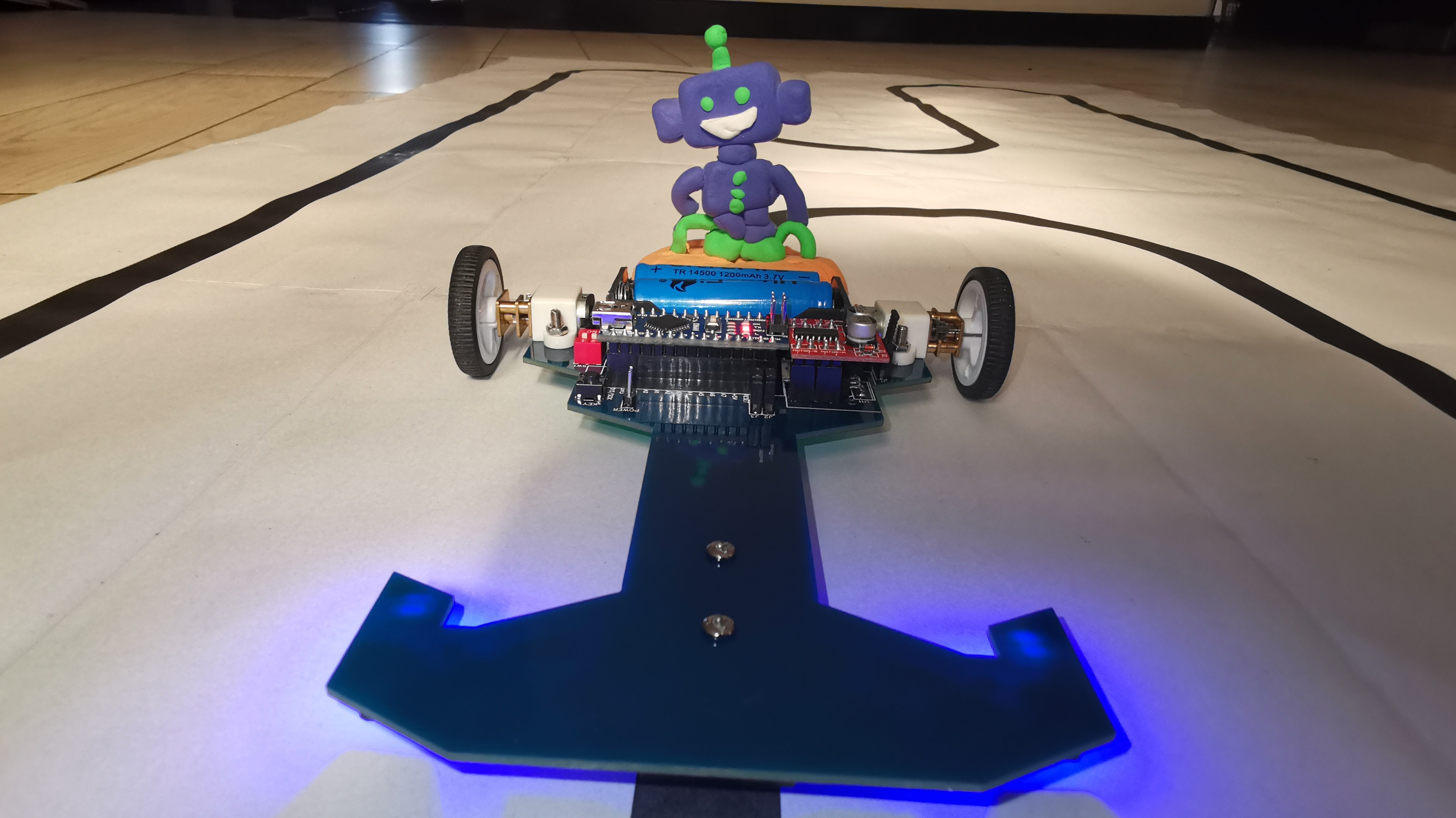
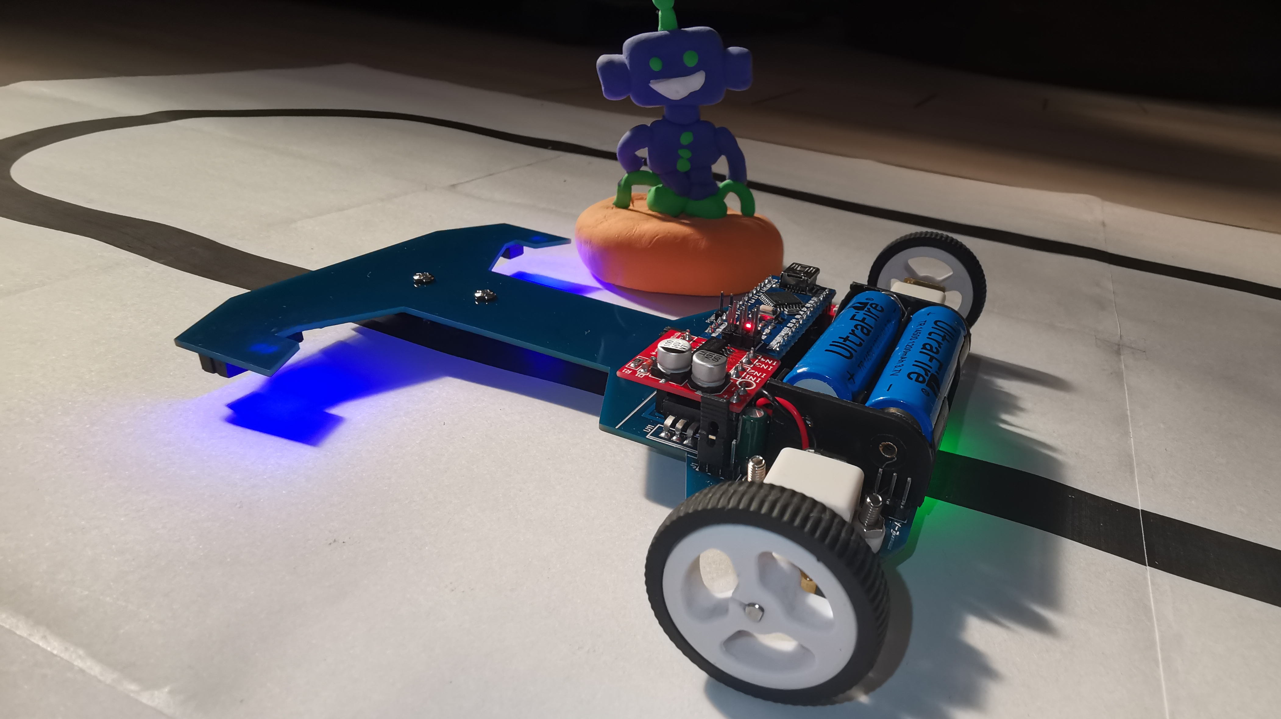
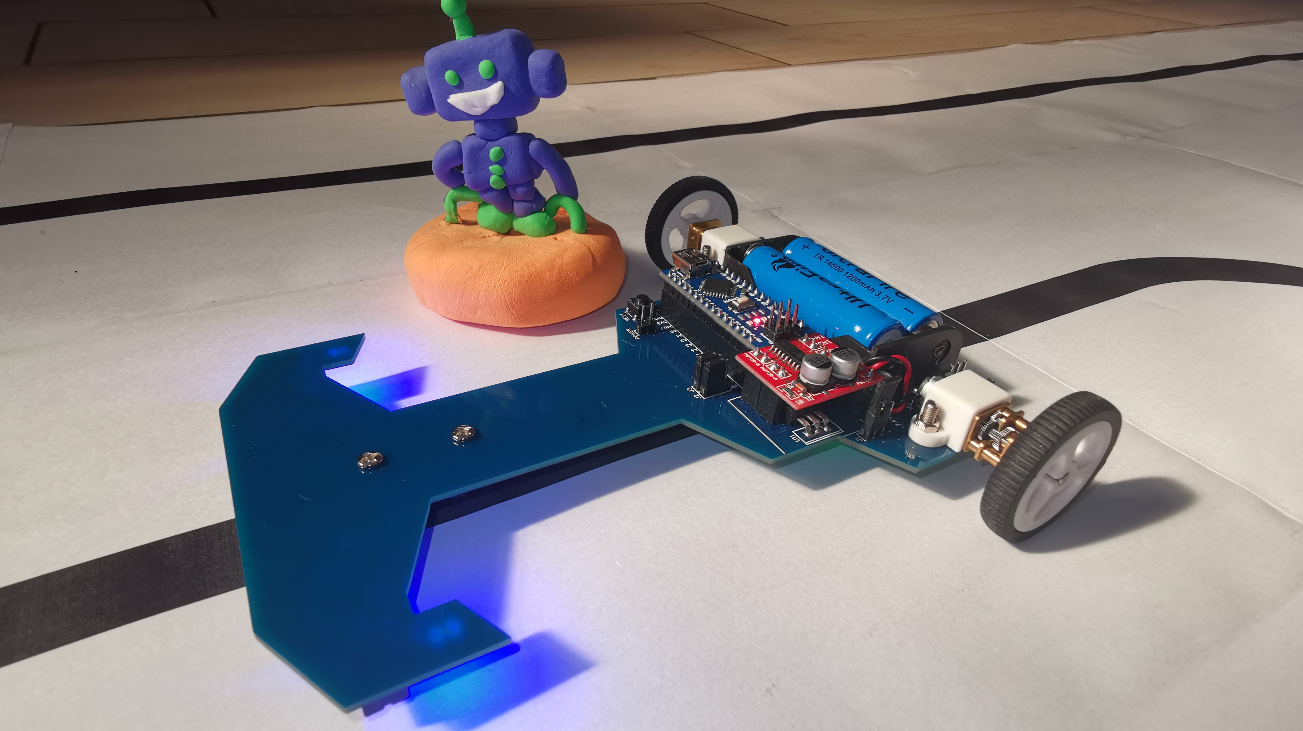
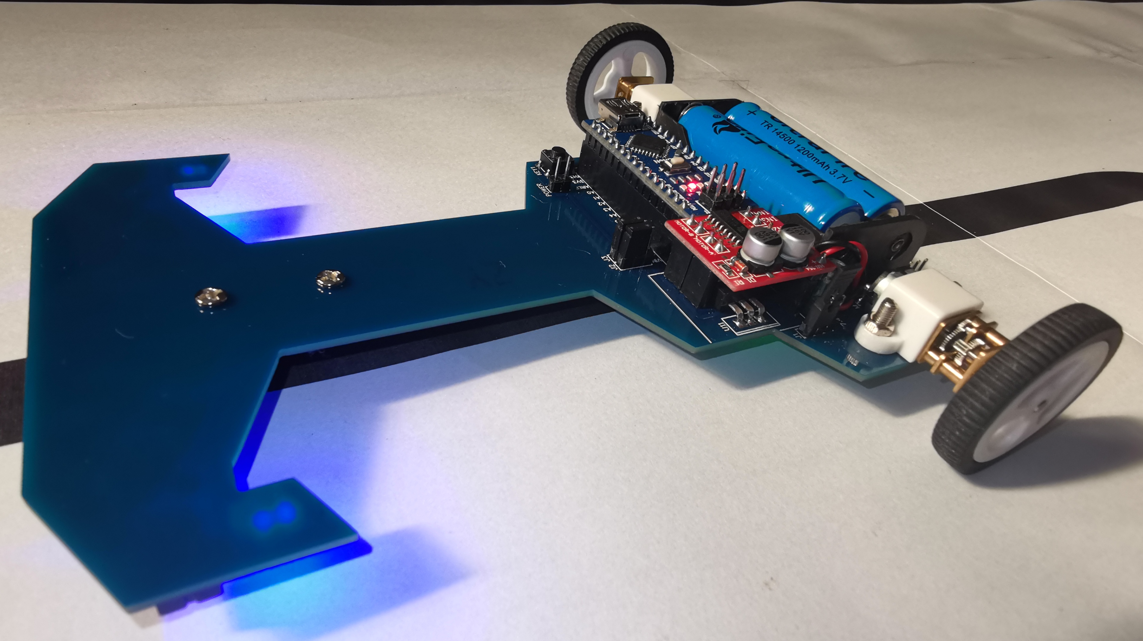
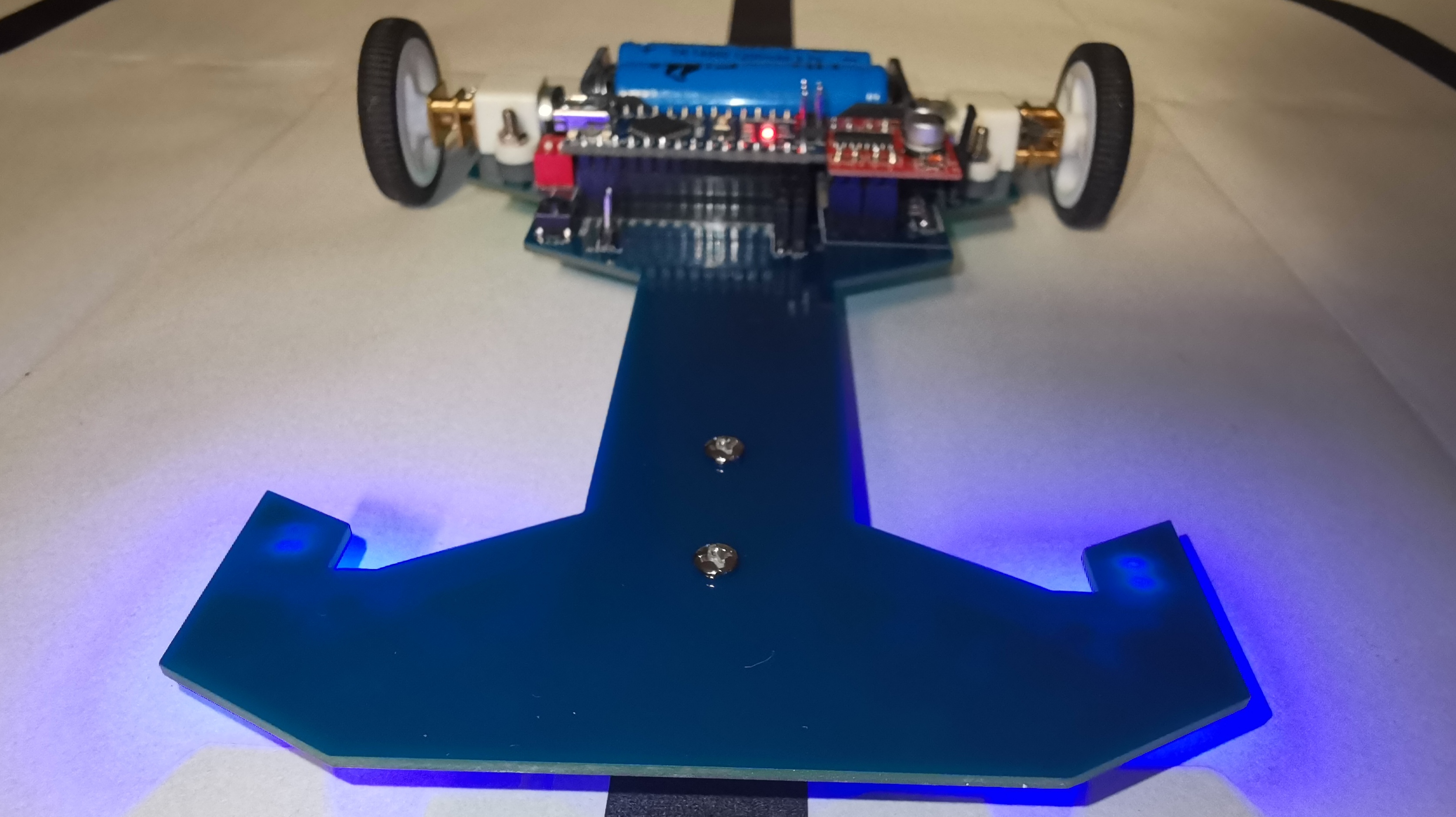
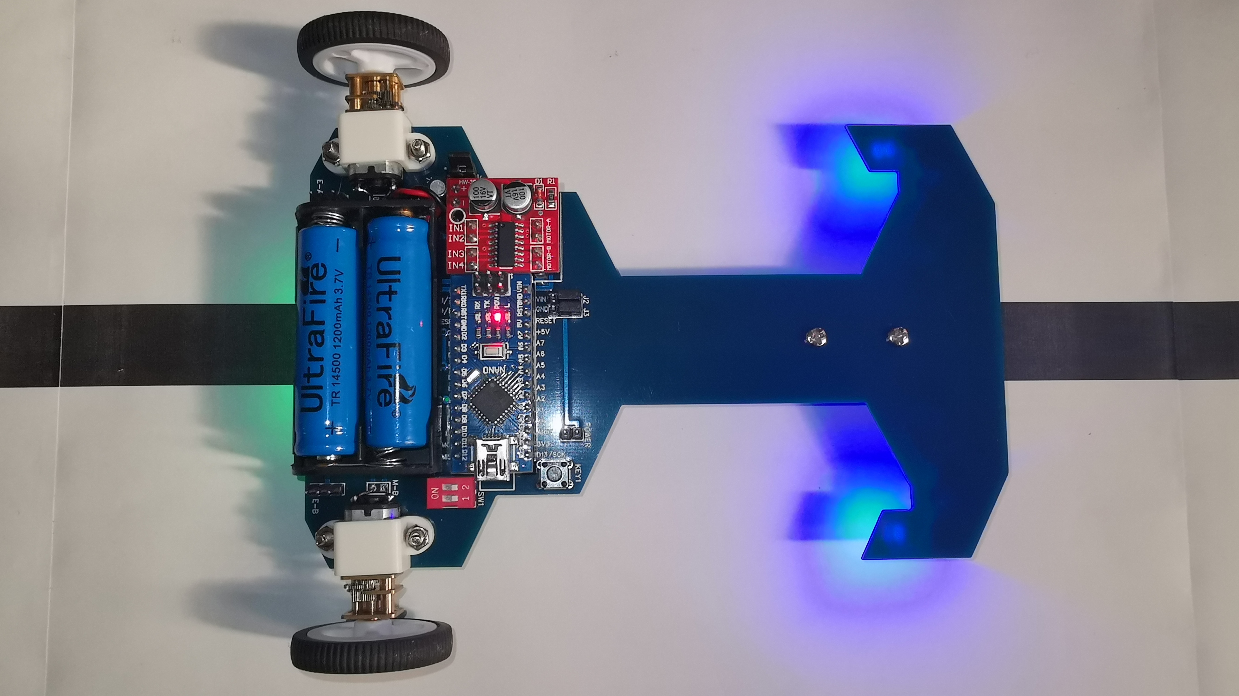
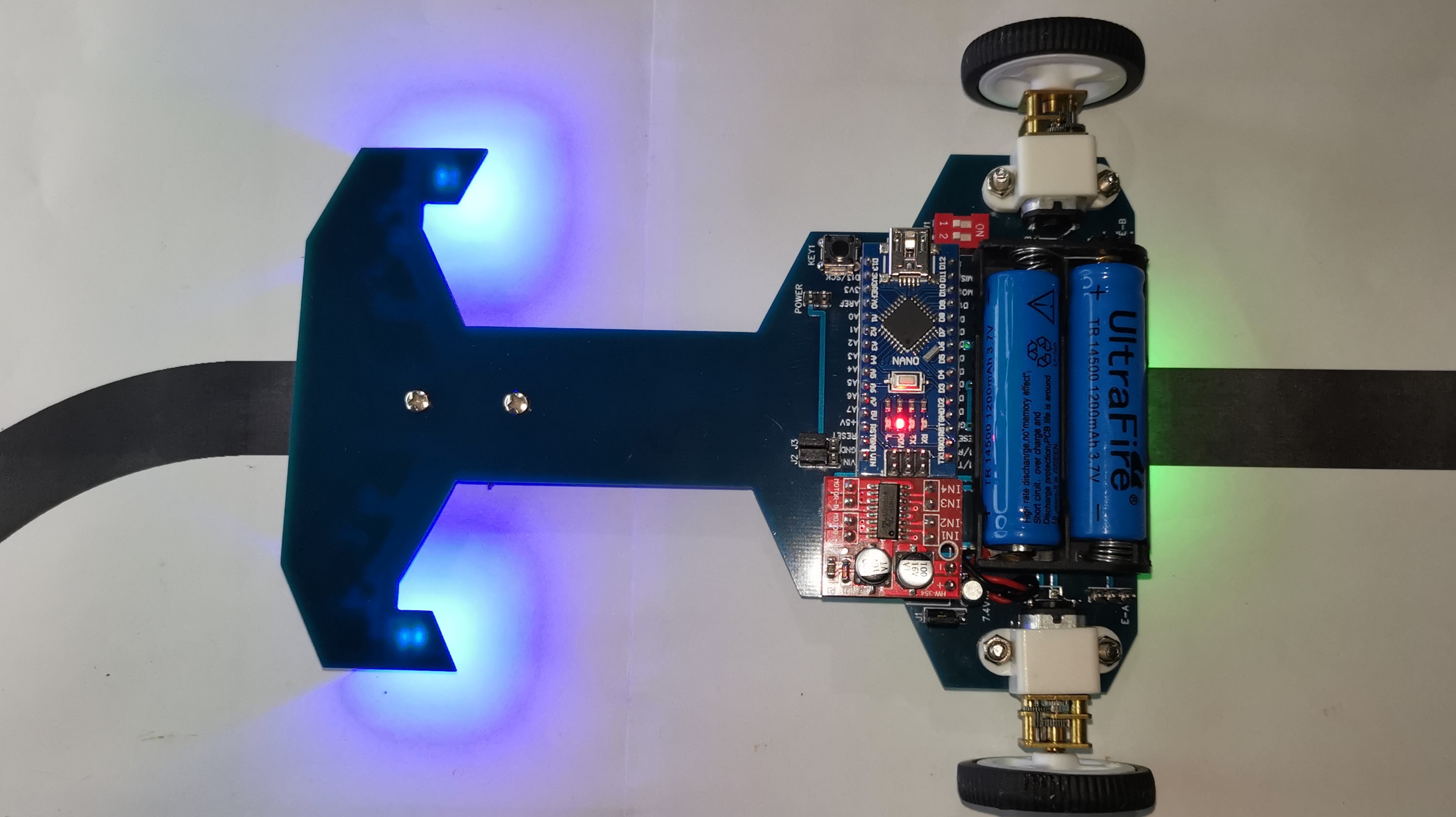
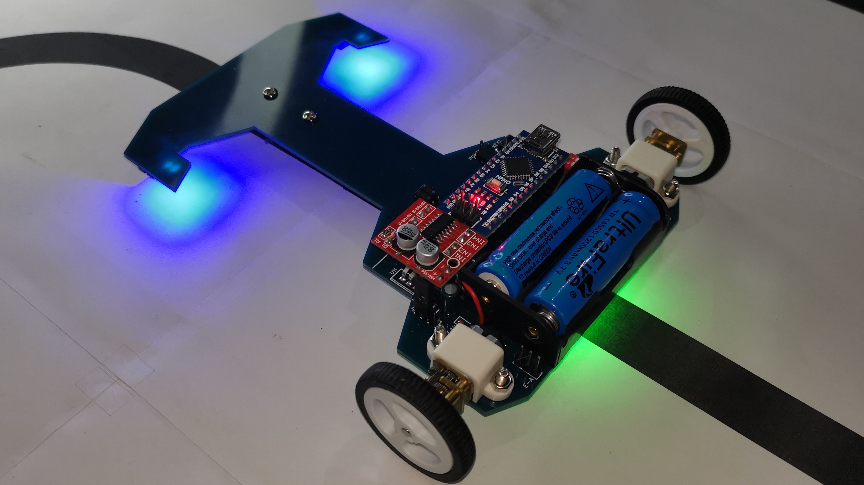
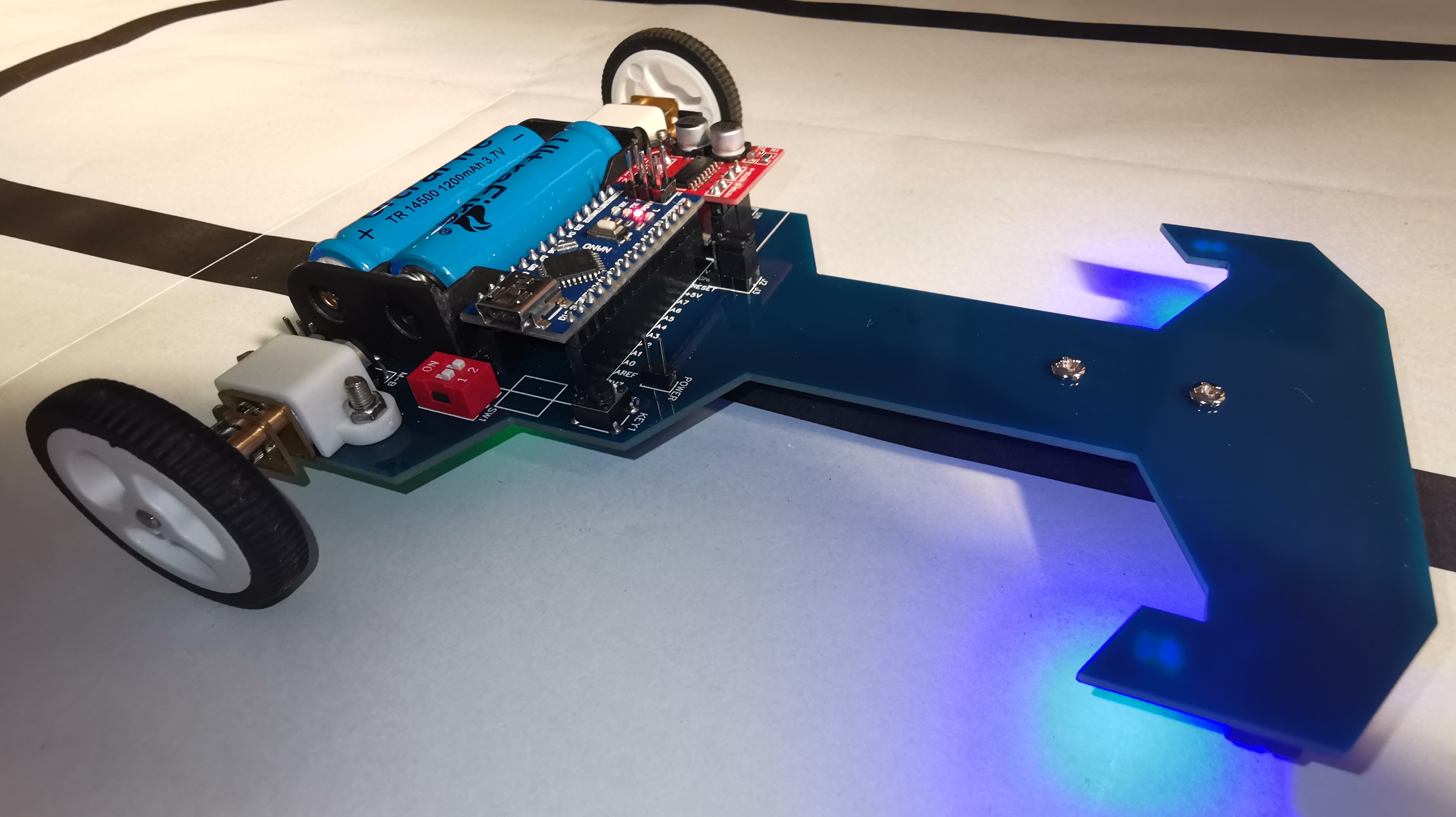
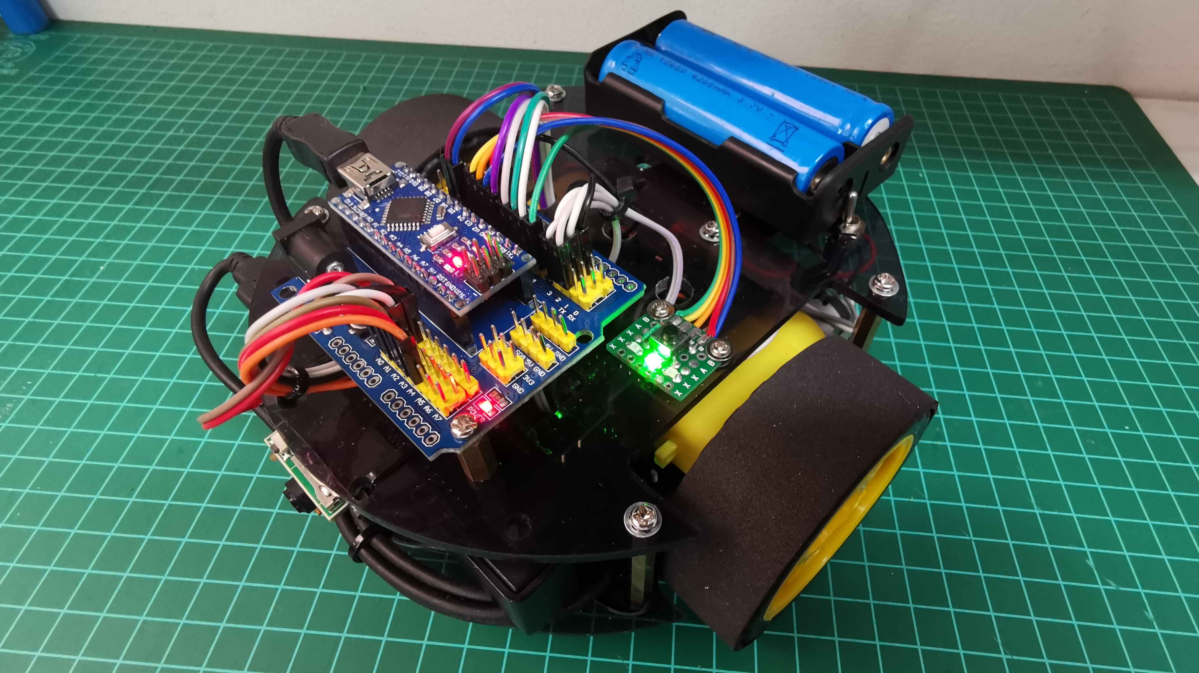
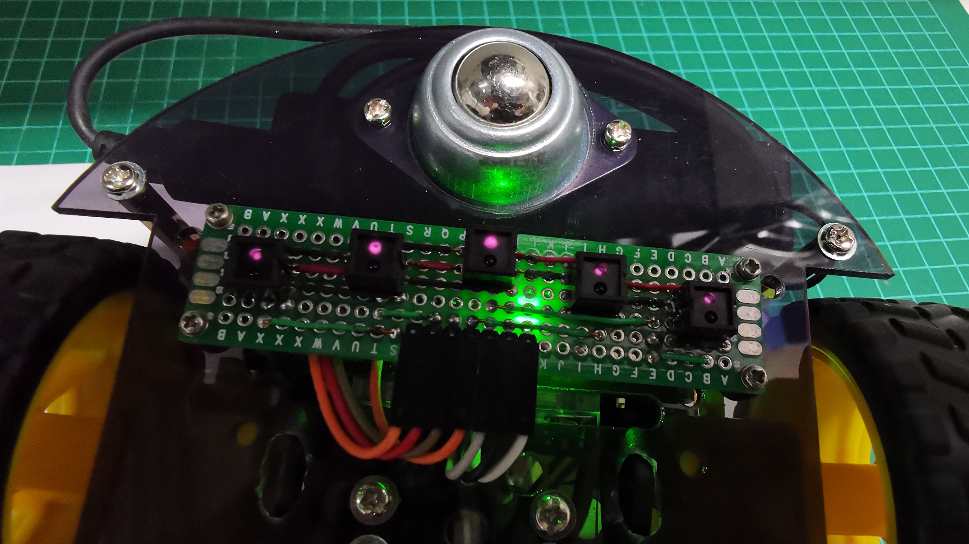
Line Follower Robot V4
Line Follower Robot V4
Line Follower Robot V4
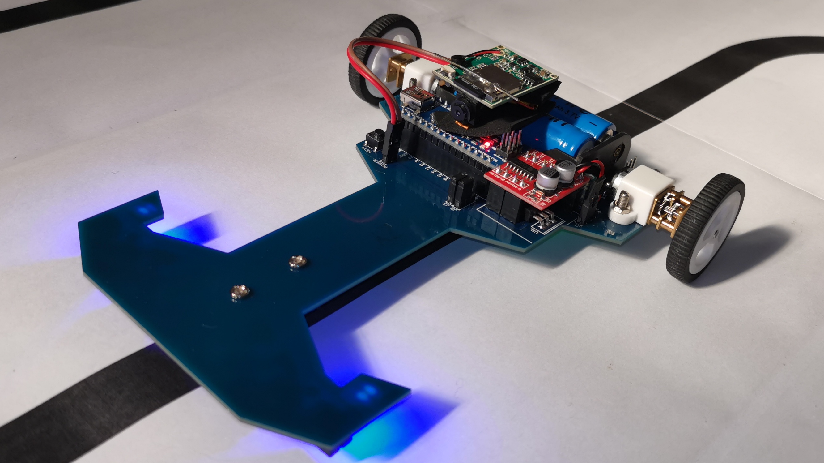
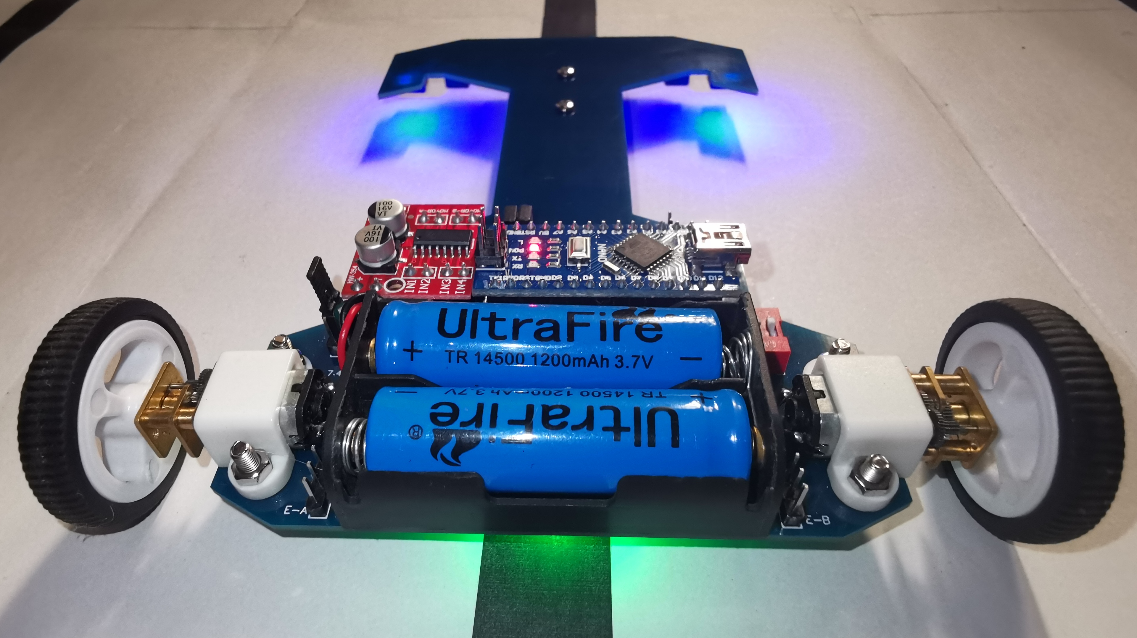
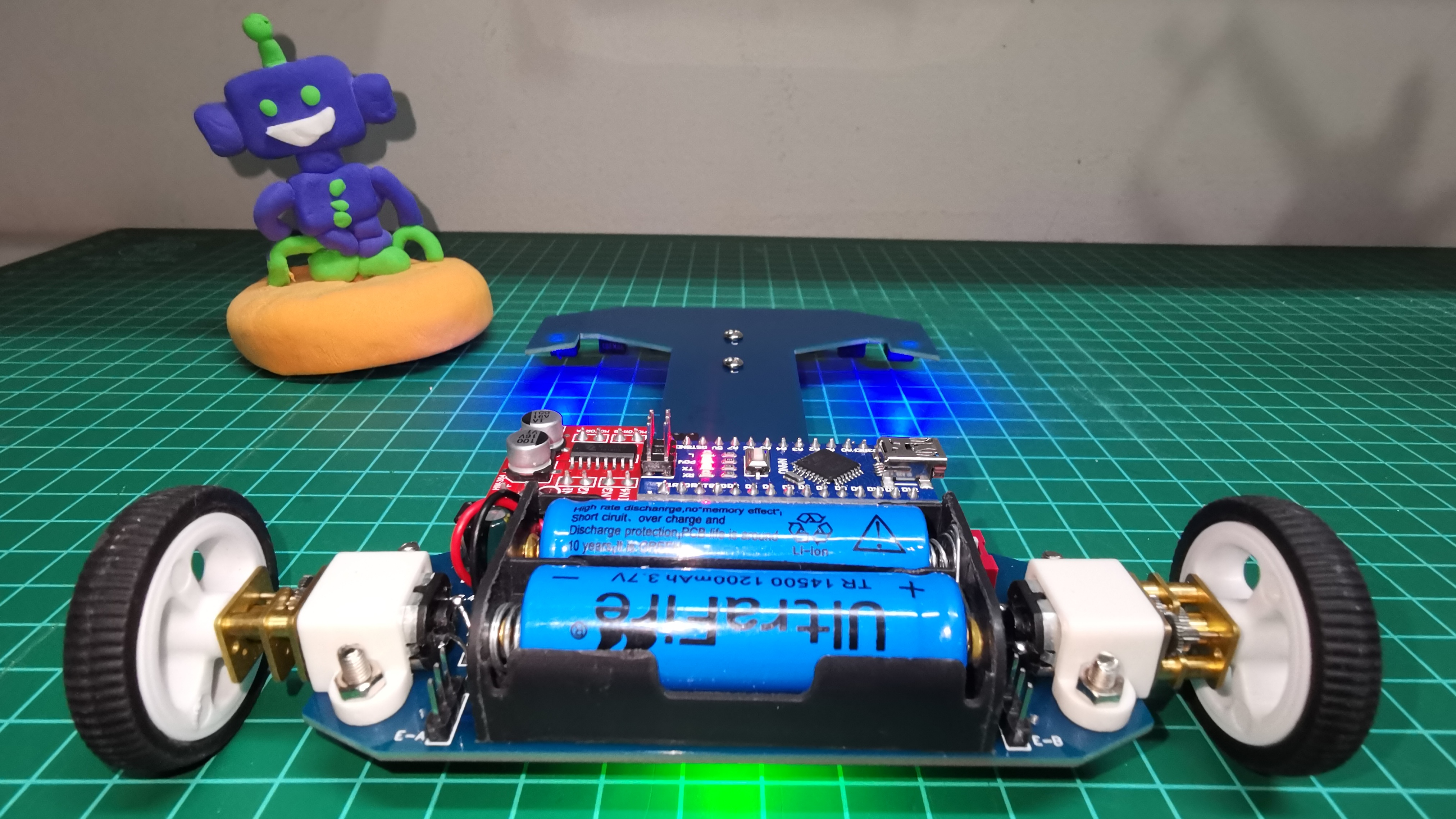
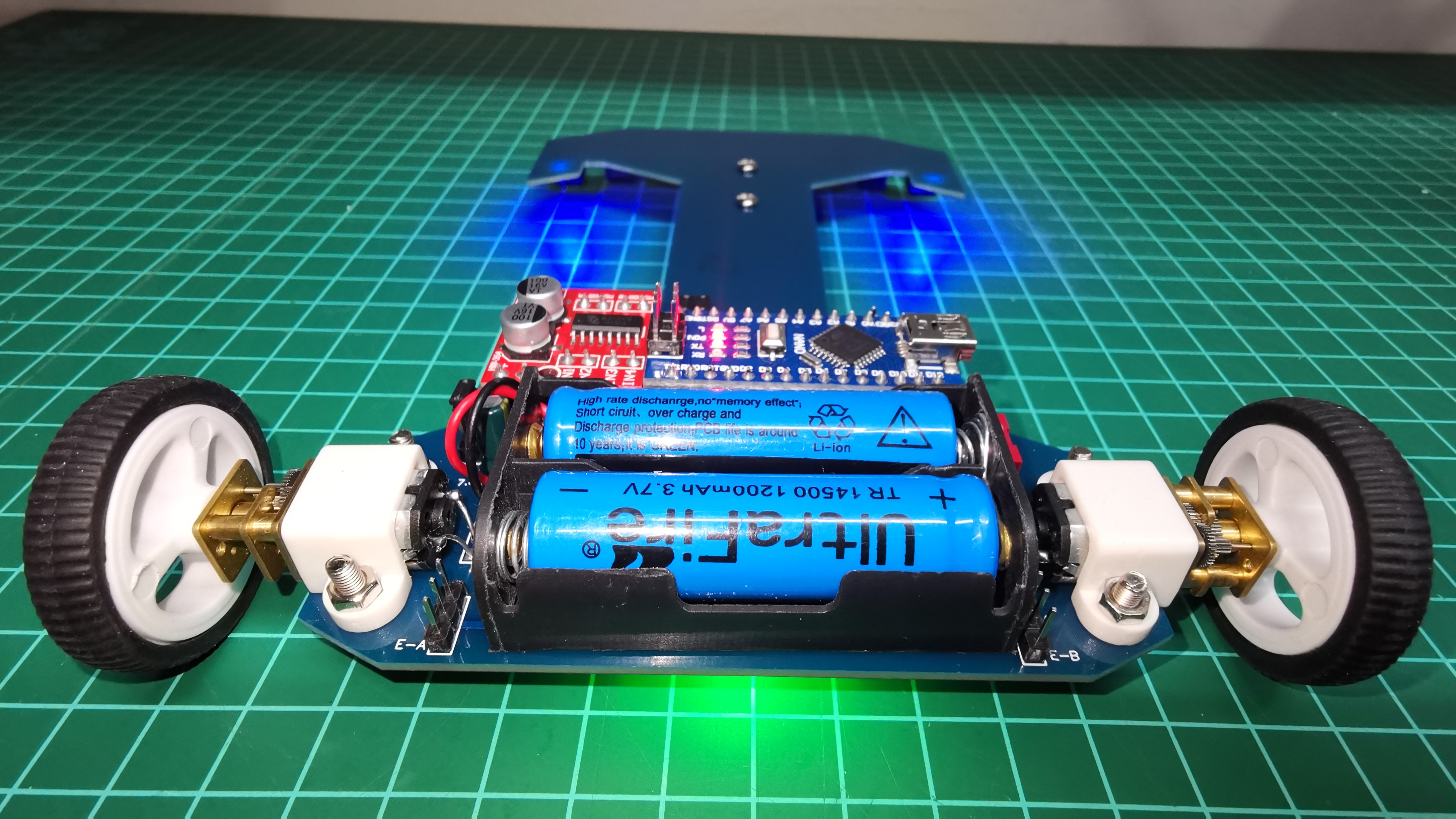
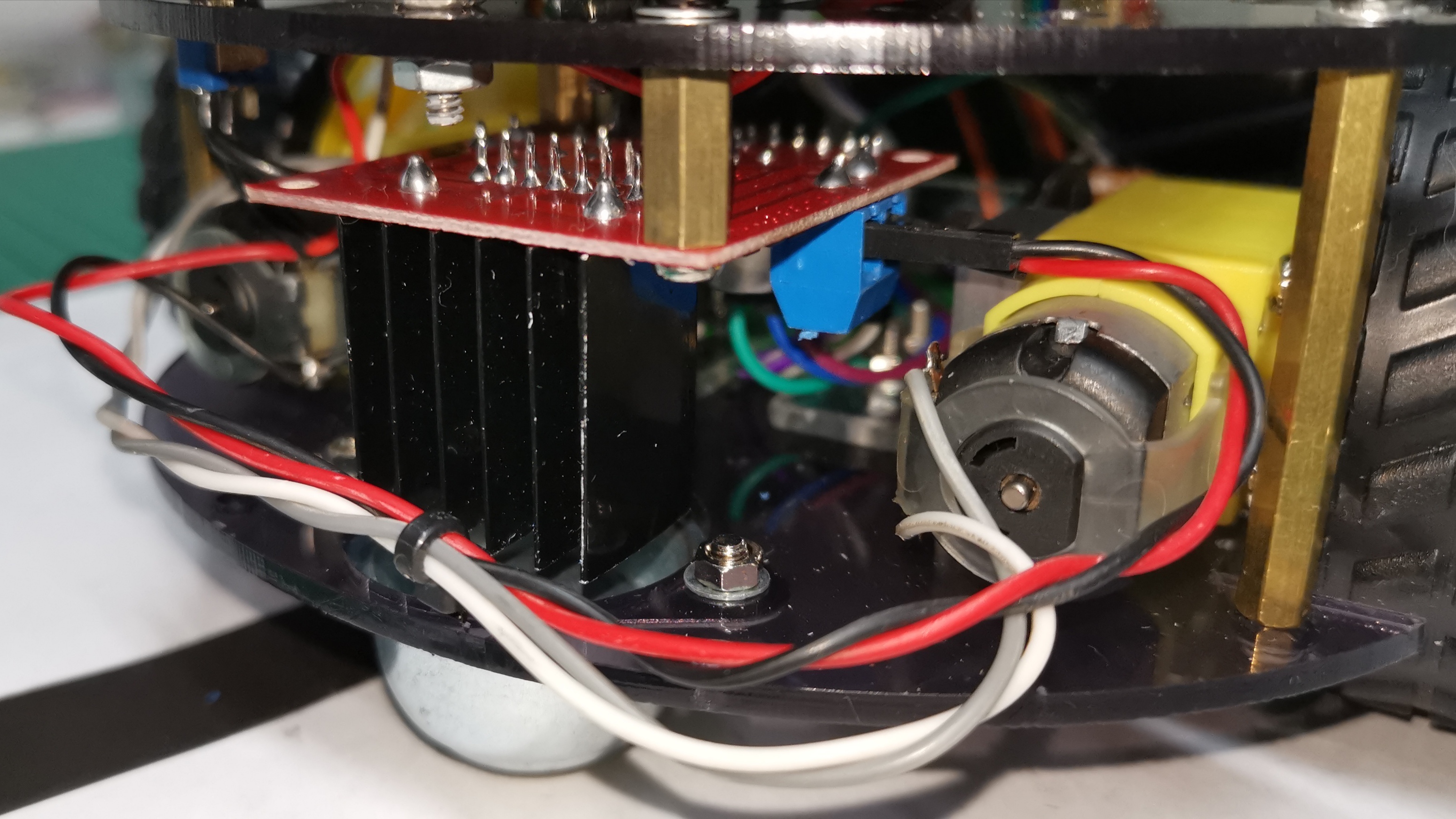
Line Follower Robot V4 (Back) L298N Motor Driver
Eva Foam Tires
Eva Foam Tires instaled
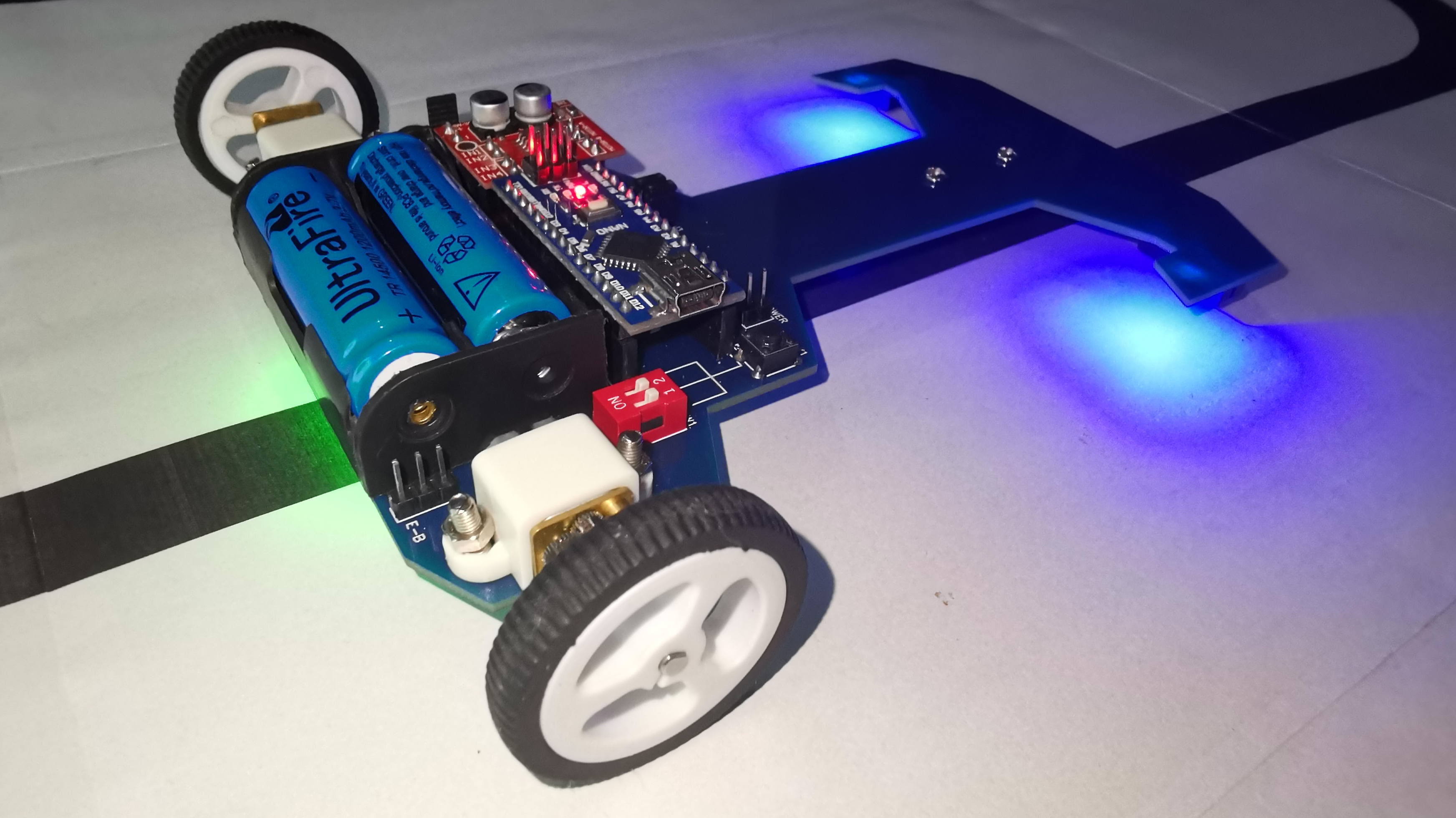
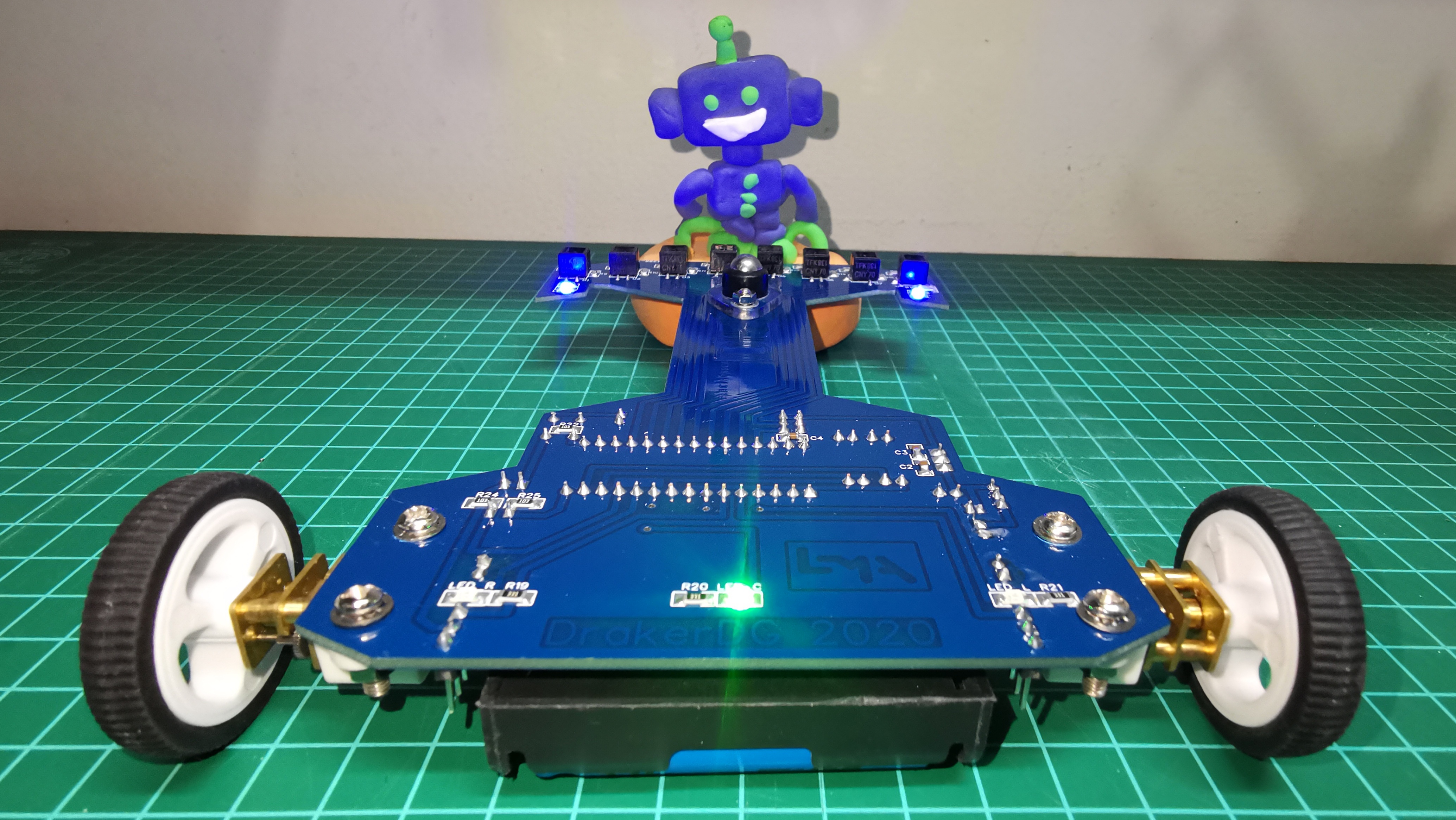
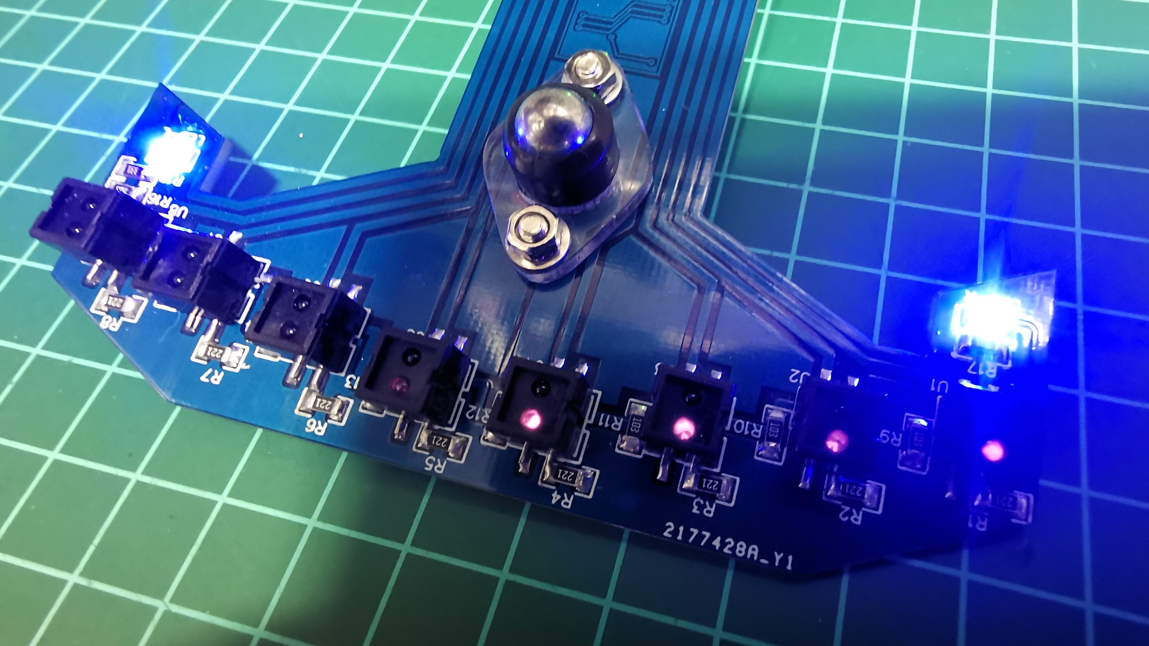
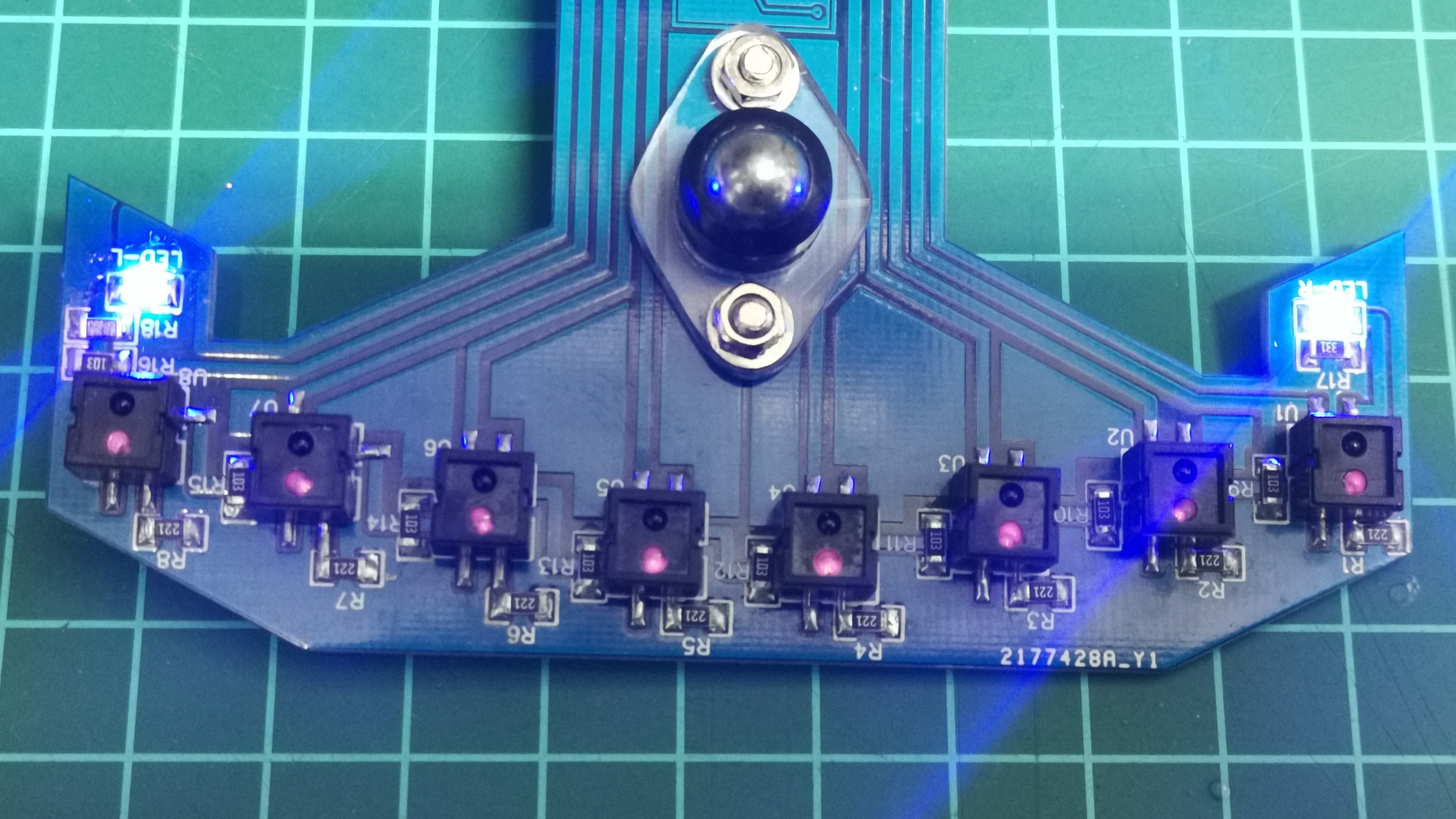
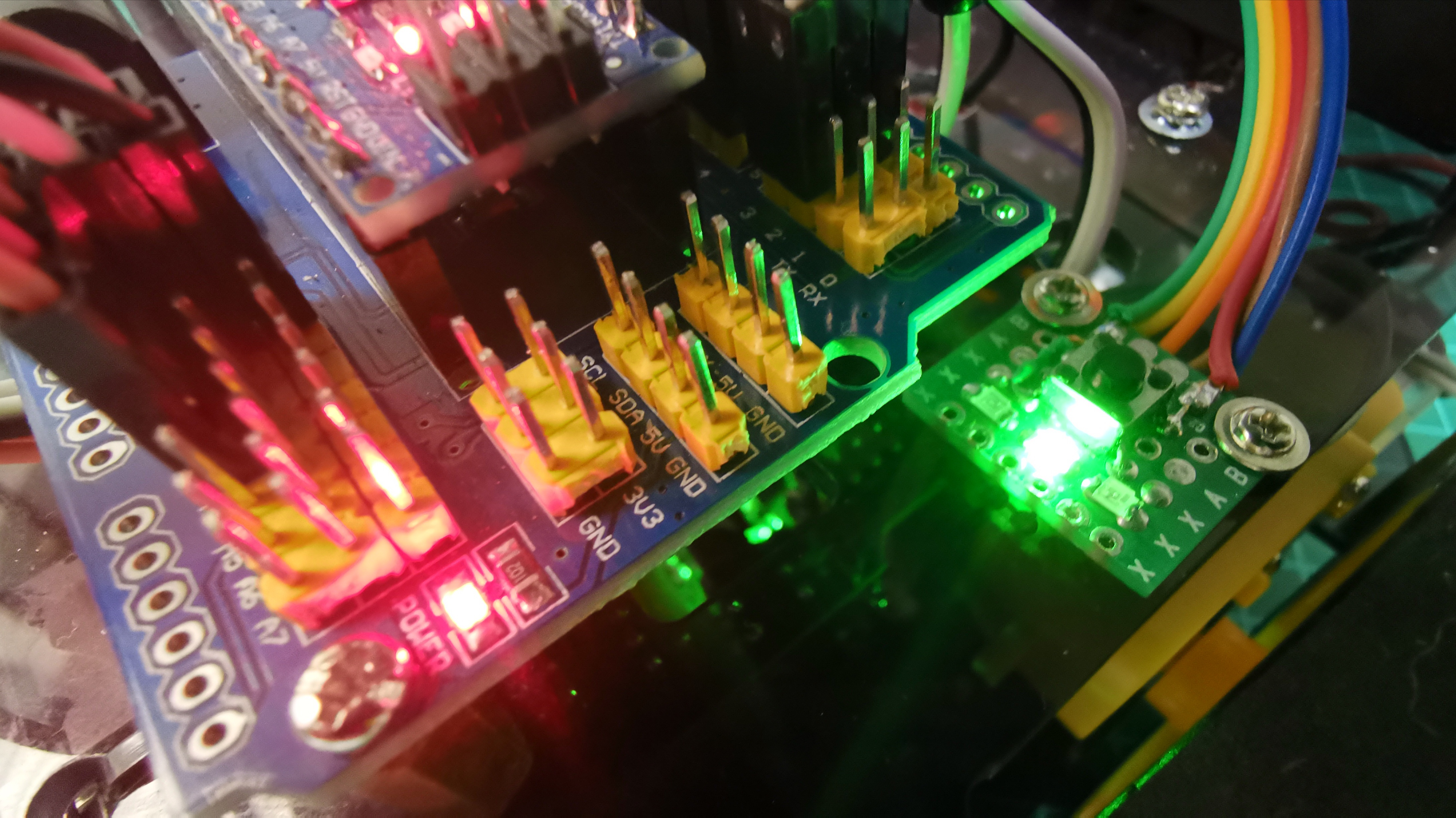
Green LED position line indicator
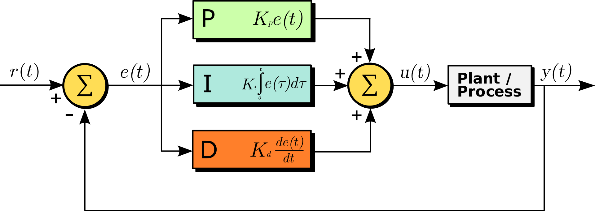
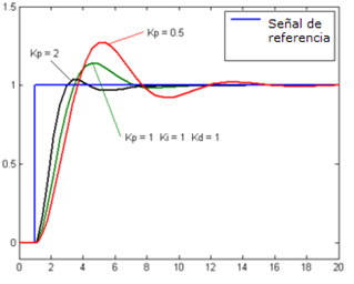
This is one of the first functional tests, in which I included the use of the programming of the PID feedback algorithm in which at the moment I use the constants P and D.
Error Correction PID
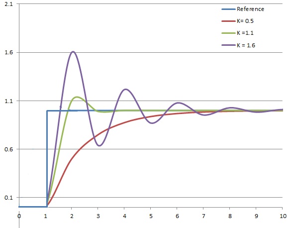
Kp constant (PID)
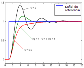
Ki constant (PID)
Kd Constant (PID)
PID Calibration Example
Adjustments regarding speed control through RPM and activate the constant I are pending.
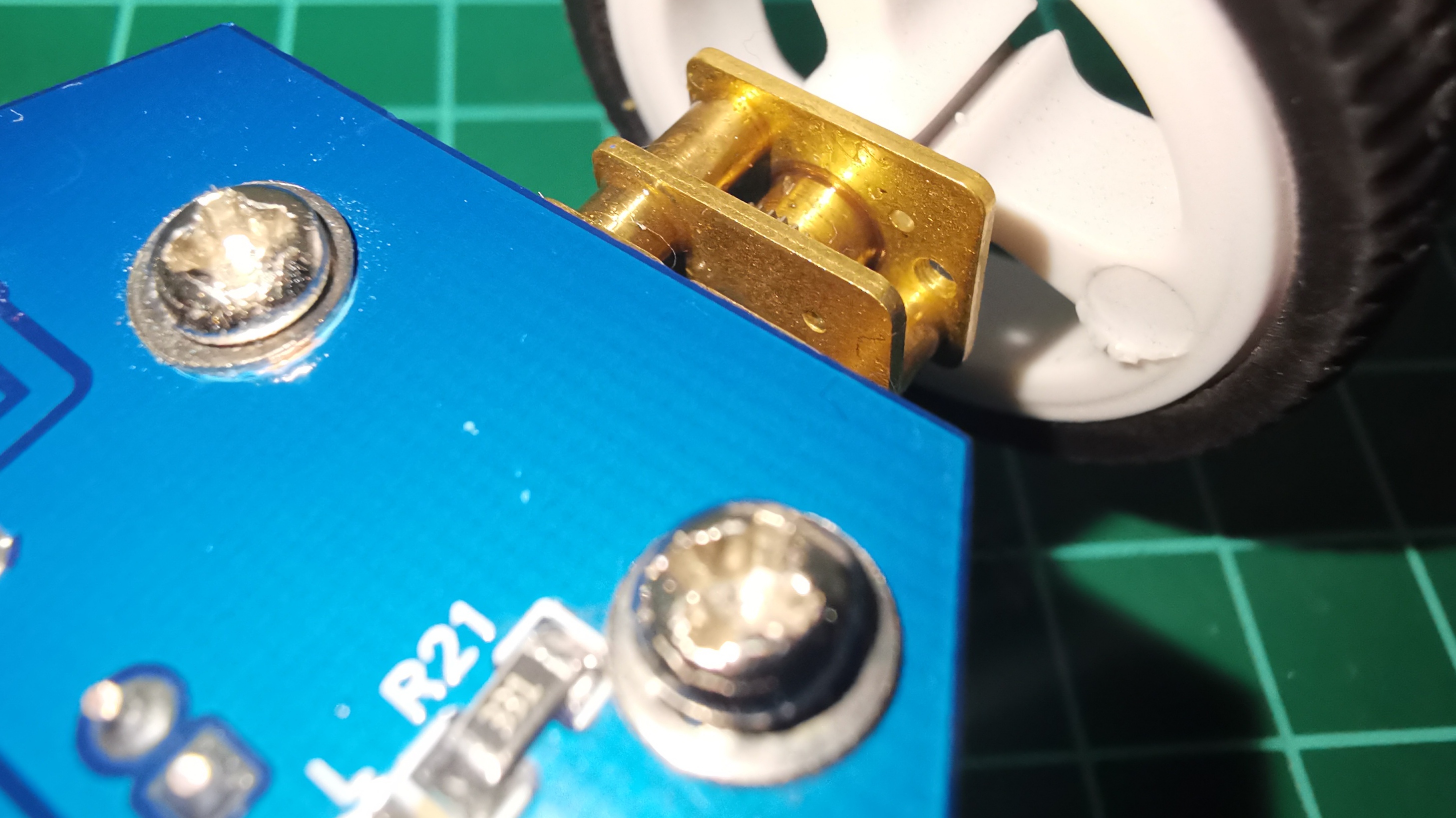
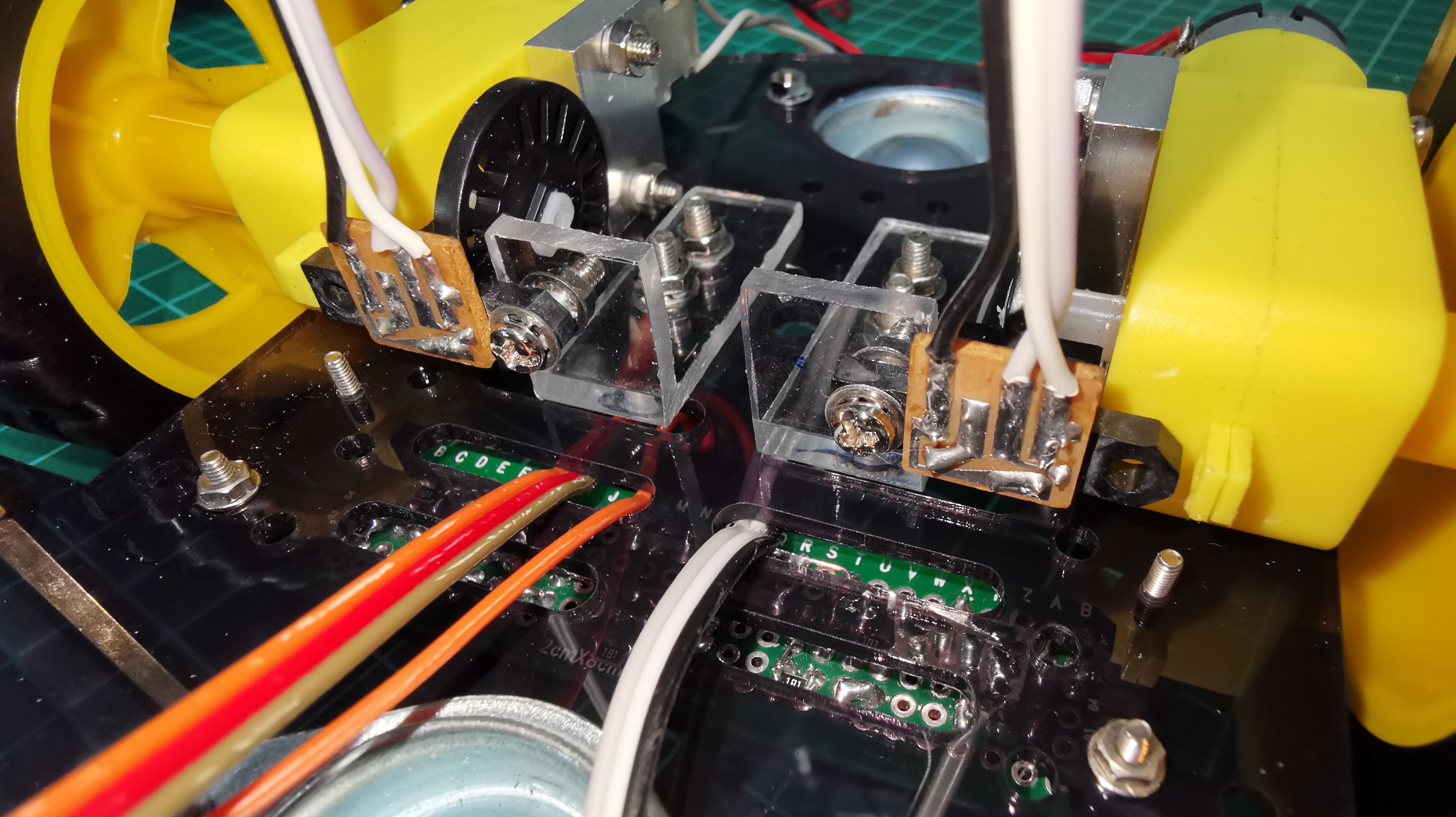
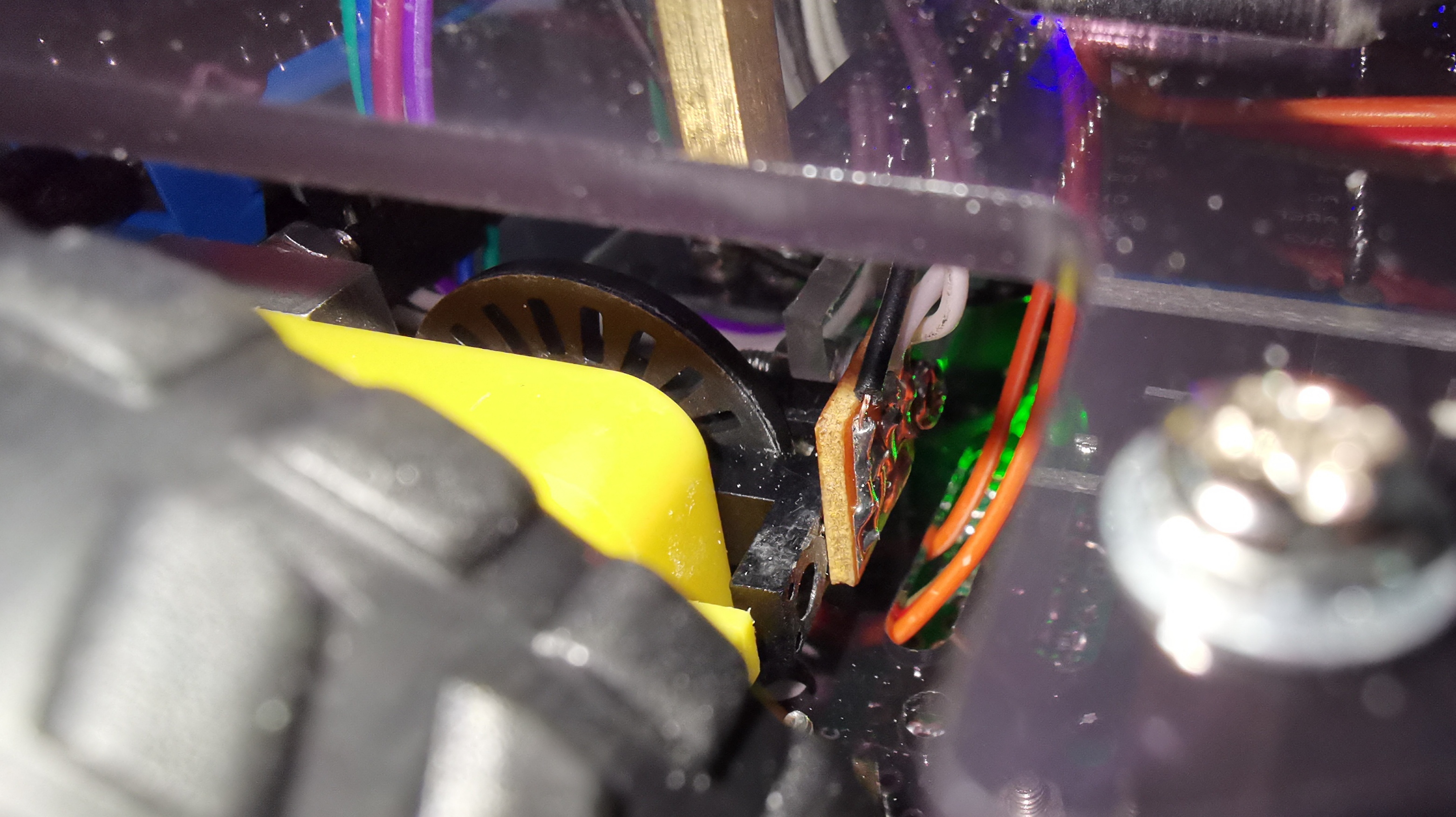
IR sensor GP1A01 (Similar FC-03) and encoder Inside
IR sensor GP1A01 (Similar FC-03) and encoder Inside
IR sensor GP1A01 (Similar FC-03) and encoder Right
IR sensor GP1A01 (Similar FC-03) and encoder Left
The sensors used five CNY70 and are read analogically. Initially it is necessary to calibrate the sensors for best performance (10 seconds).
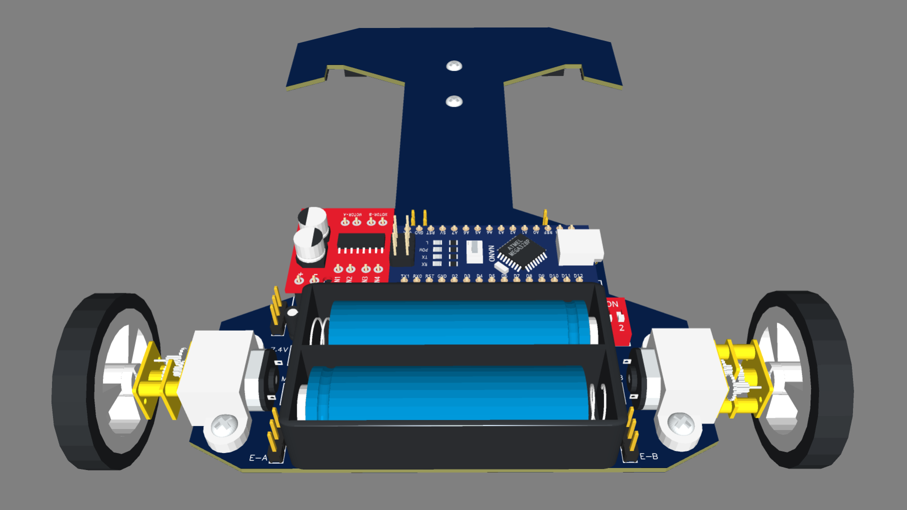
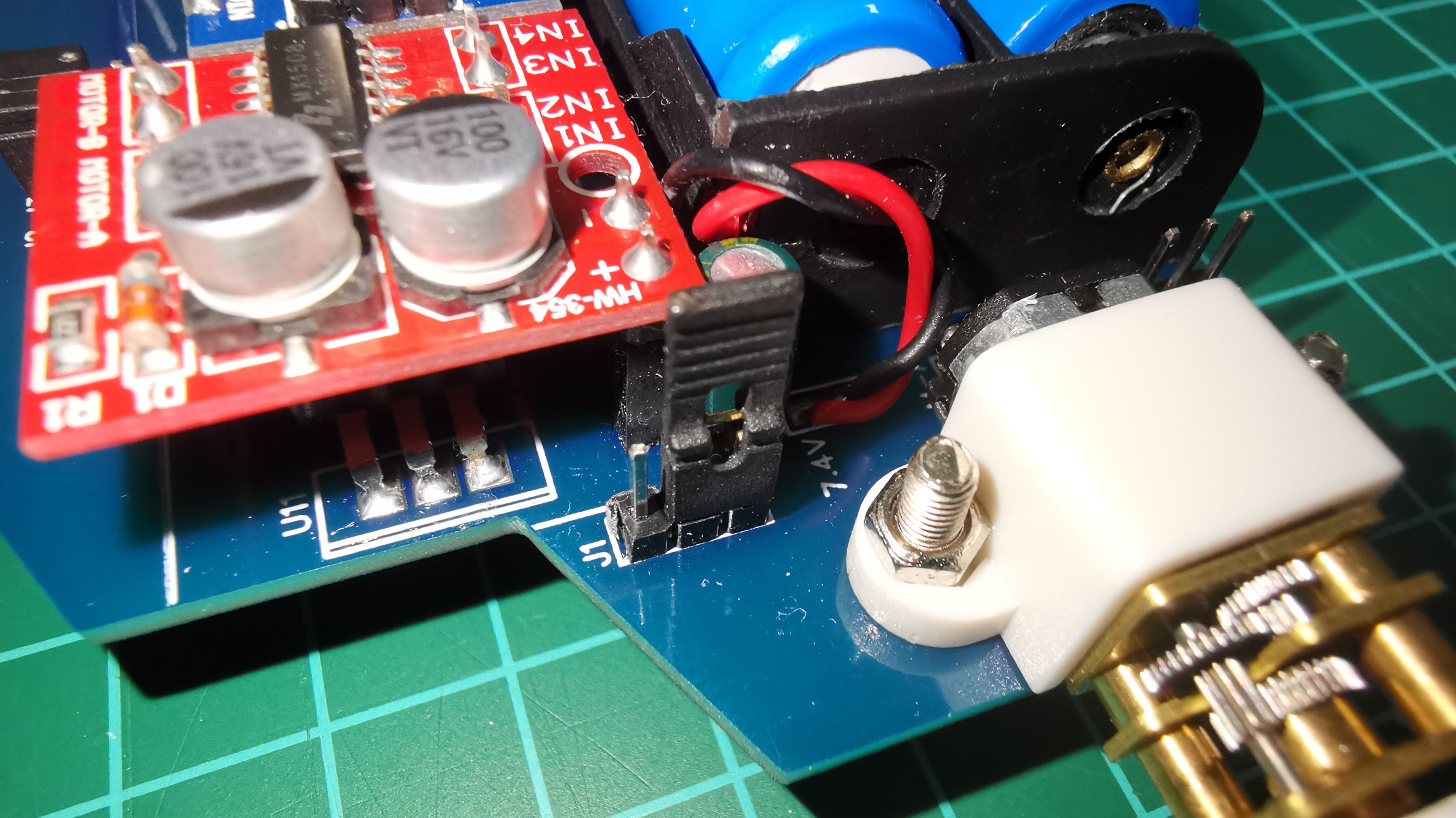
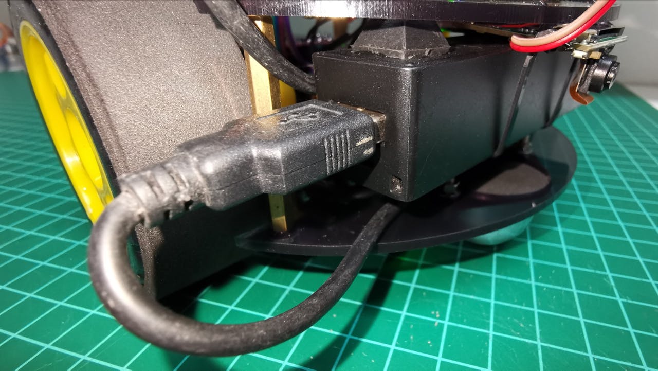
The motors are powered by 2×3.7V 4200mAH 18650 batteries in series (7.4V) and for the control part (Arduino Nano) I use a 5V USB portable charger.
2×3.7V 4200mAH 18650
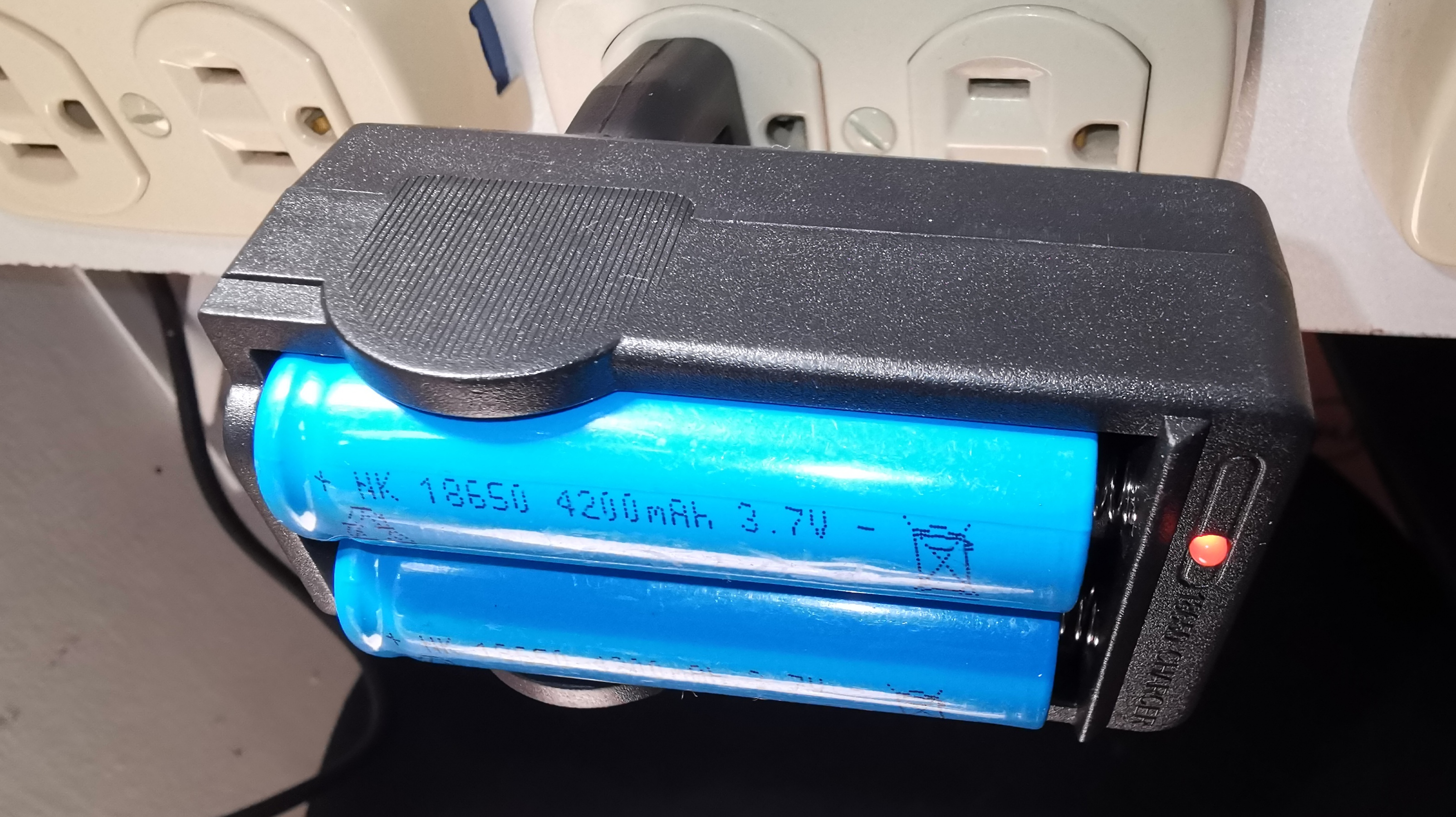
2×3.7V 4200mAH 18650 Charger
5V USB portable charger
5V USB portable charger
5V USB portable charger
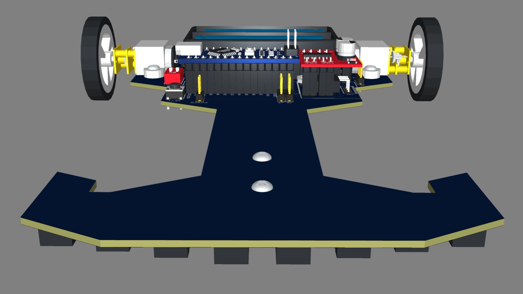
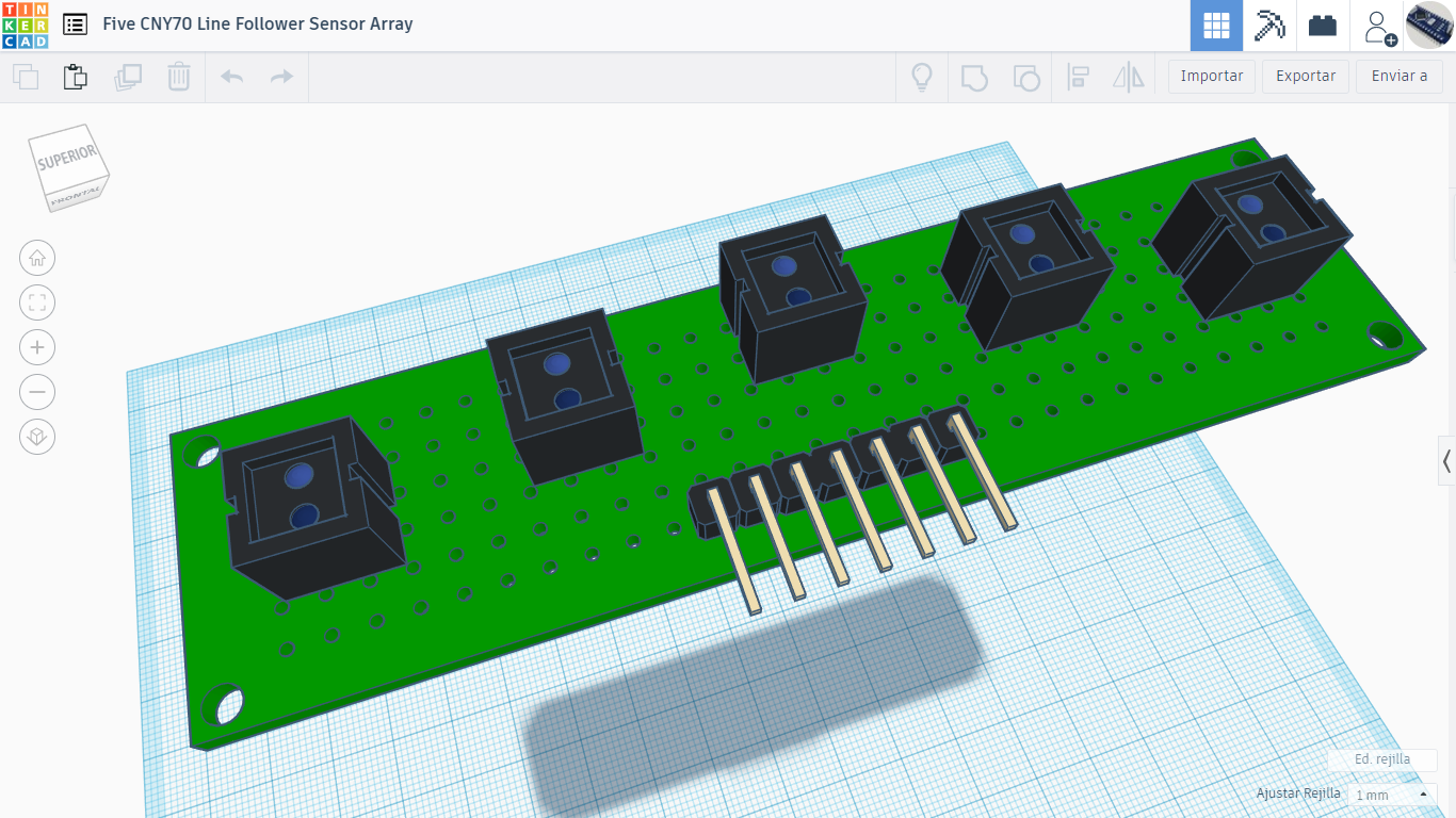
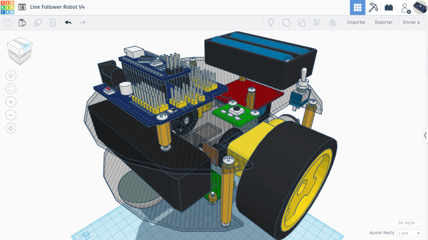
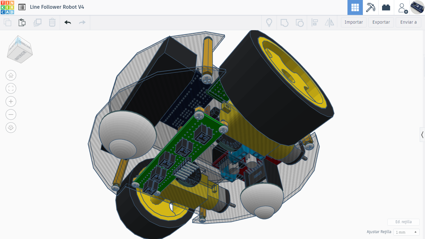
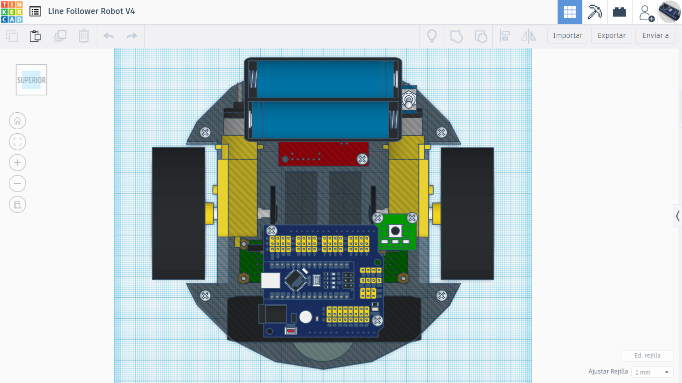
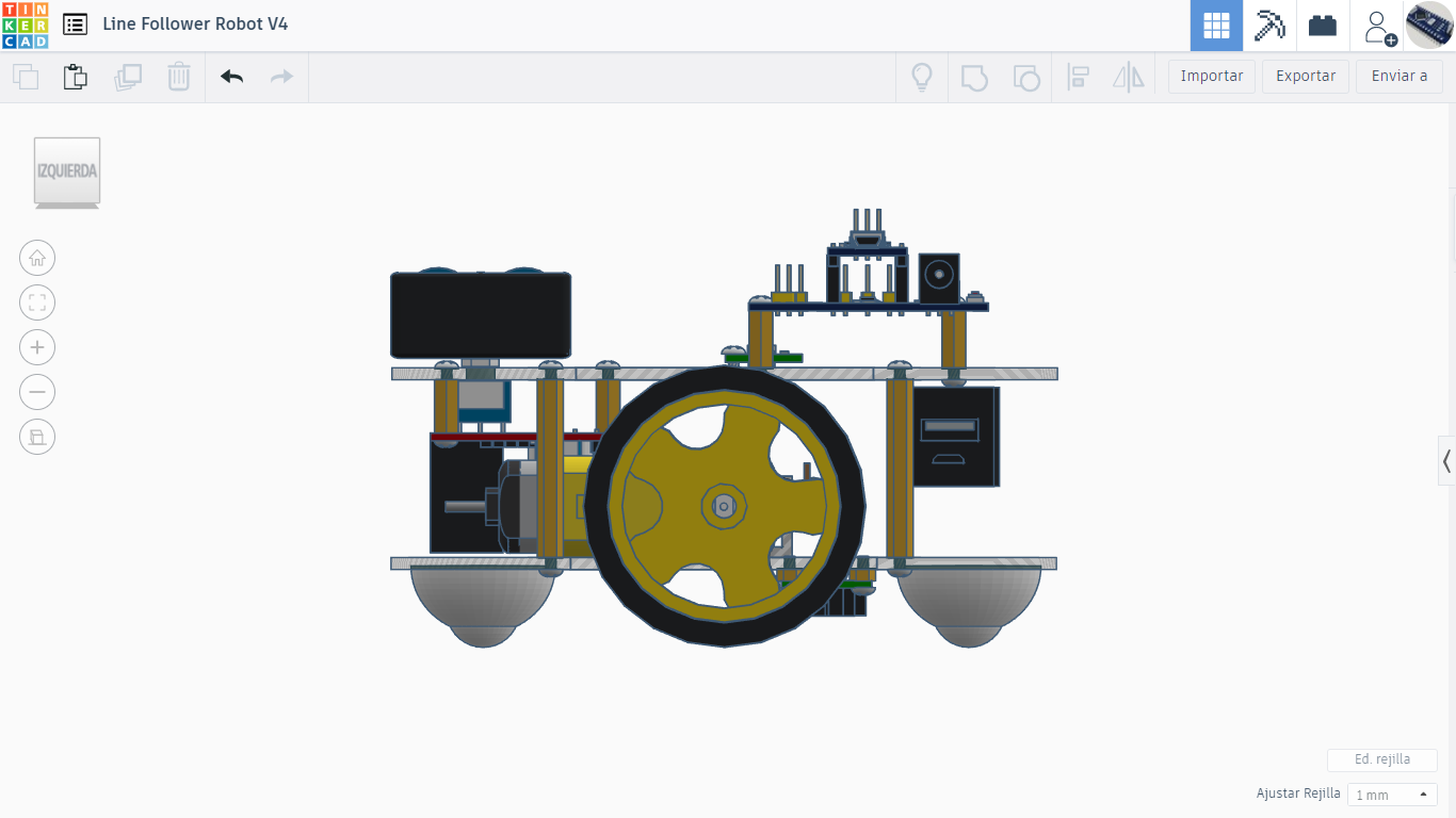
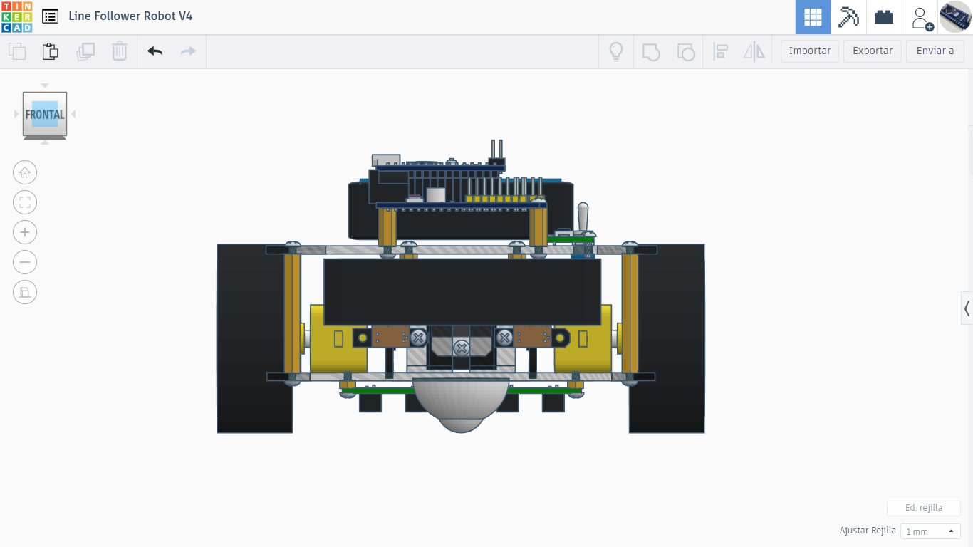
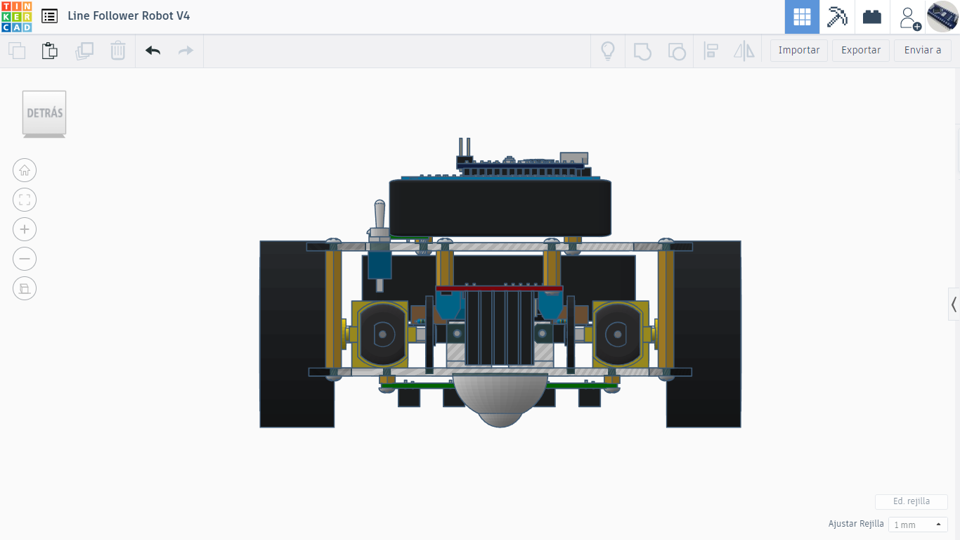
I include the physical design made in TinkerCAD
TinkerCAD Design
TinkerCAD Design
TinkerCAD Design (Top)
TinkerCAD Design (Left)
TinkerCAD Design (Right)
TinkerCAD Design (Front)
TinkerCAD Design (Back)
TinkerCAD Design (Bottom)
I have made some templates with which depending on the way they are placed, any size of track can be made. I have done 2, but the limit is imatination.
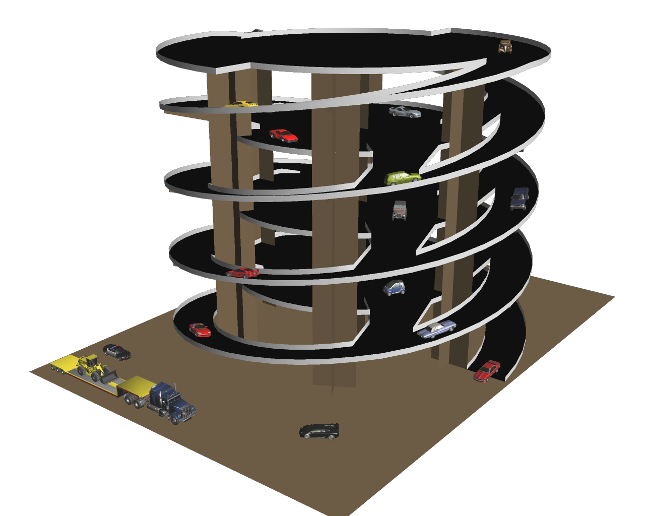
This is another model that you chose my little boy of 14 that are available on a page of Carmageddon papercrafts, with respective links to download.
This is the direct link to download the Abba Cab:
Both the game’s website are for anyone 18 years, the role models are beautiful. While most are simple, so much that my son picked as the Big Dump (A3), need instructions for assembling them.
For this reason I am not 100% that should unite parts where they were assembled.
These are some pictures where I show the assembly process:
These are some pictures where you can see the finished model including a couple of buddies as passengers:
This is the direct link to download the PDF template:
In the following pictures you can see the steps to be joining parts of the model.
This is the finished model:
This model can be used as finger puppets. In the website of origin, there are other models as bamby in the same style.
Hope you like it, and my son likes.
Now it’s time is a classic character, this is Super Mario, in the version used in the Nintendo Wii game consoles.I first began to document with pictures I found on Google. Since I have extensive experience in 3D design from Metasequoia, I chose a symmetrical and there is also another view of the drawing, which in this case was a side view.These are the pictures chosen and although the image from the side view is not 100% fit with the image of the front view, is a good reference to achieve the approximate volume.
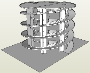
The following images are renders made from Metasequoia, which shows the dimensions achieved in 3D based on 2D views and different views on the design of the finished model.
The following video shows some details of the design in 3D from Metasequoia.
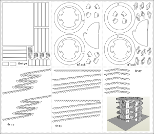
With 3D design, made in Metasequoia, load it in Pepakura to unfold the design and to design templates, ordering all parties and grouped by color.
The following file is the template group in both color and black and white:
Original file format is PDO, can be downloaded from the following link: Smario01B.pdo(zip file).
Following video shows how the pieces fit together, from different parts of the model of Super Mario in Pepakura software.
Now is time to bring the colored paper to print the template group and then cut, foldand glue and create the papercraft design model of Super Mario.