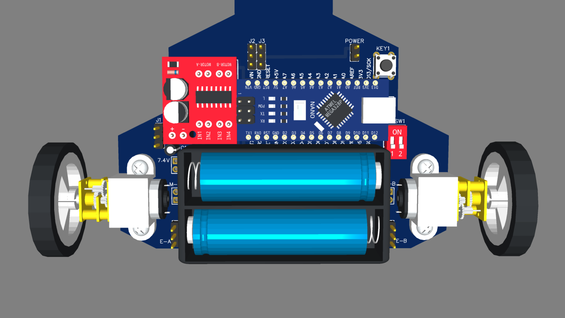
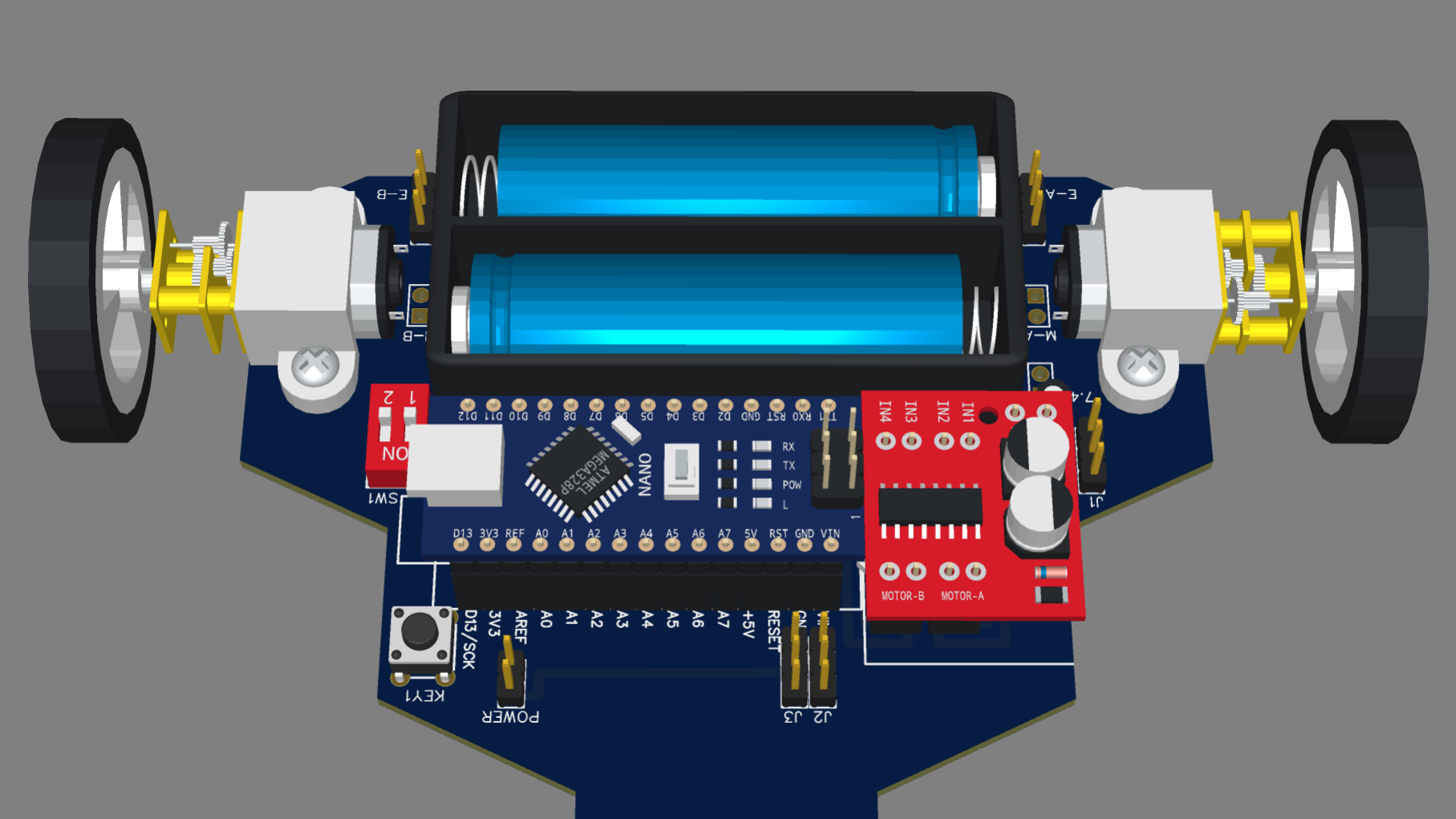
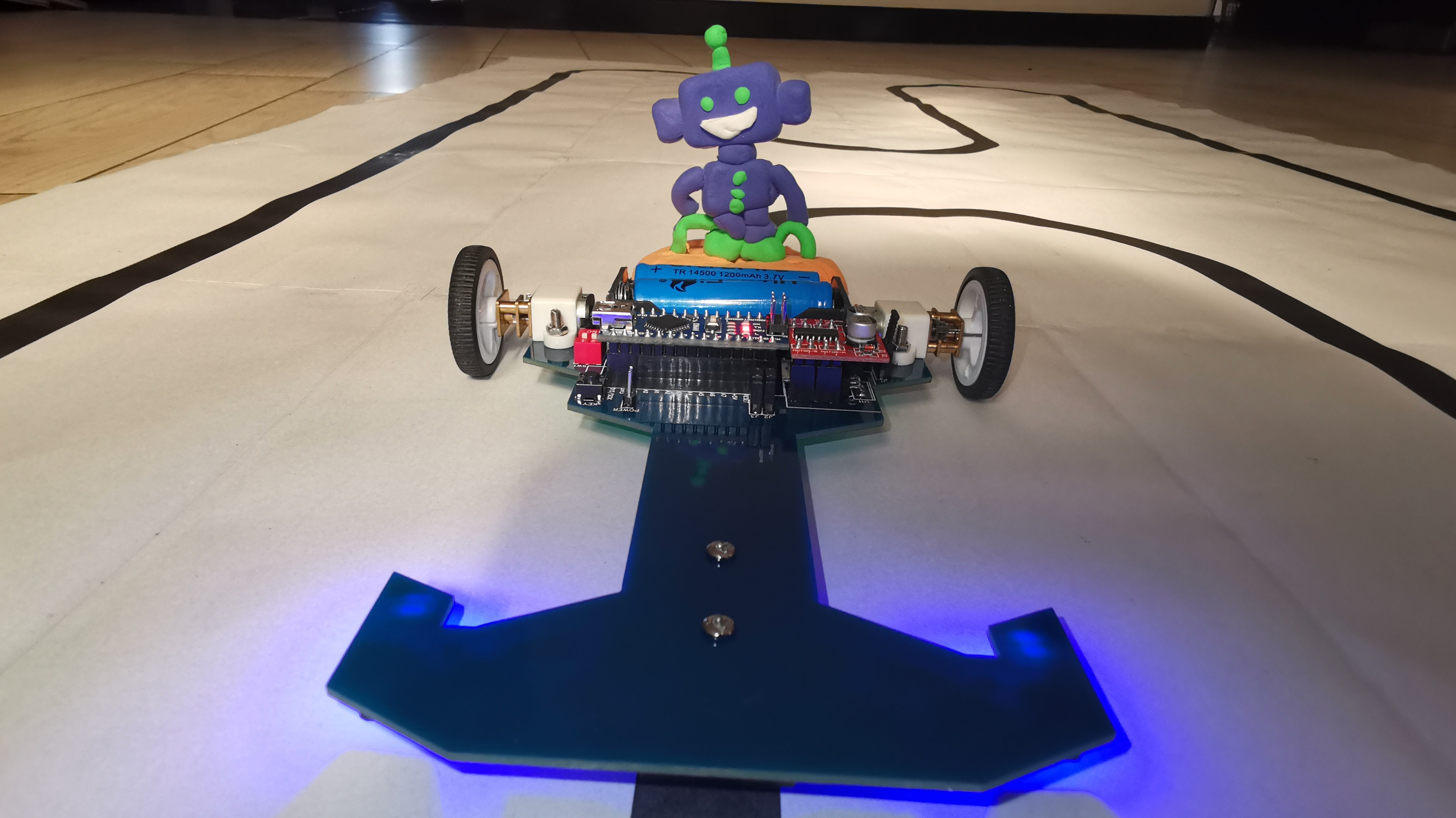
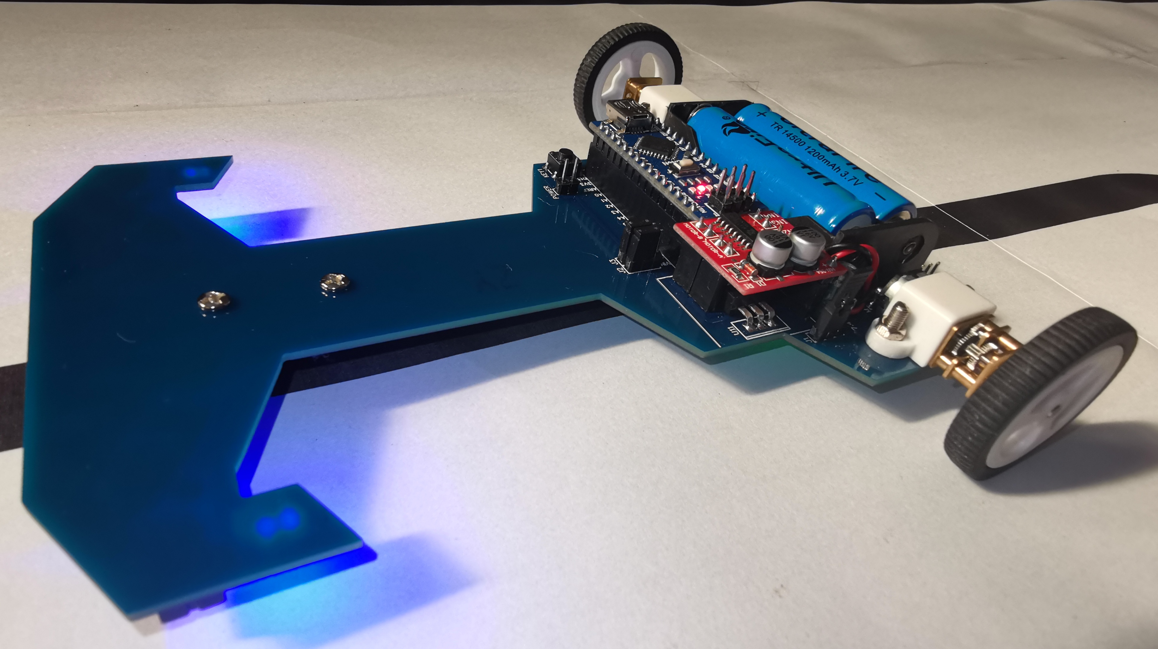
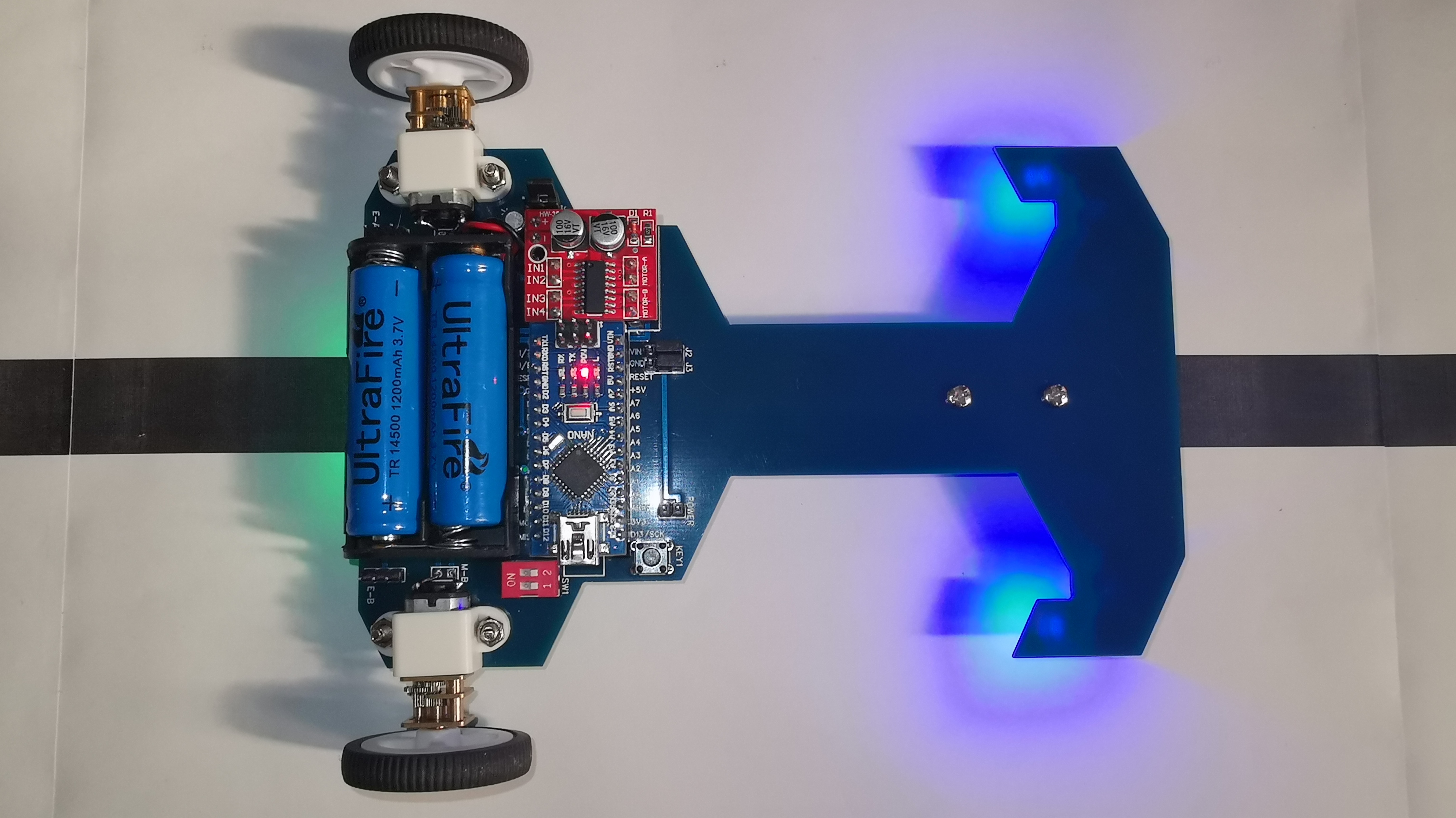
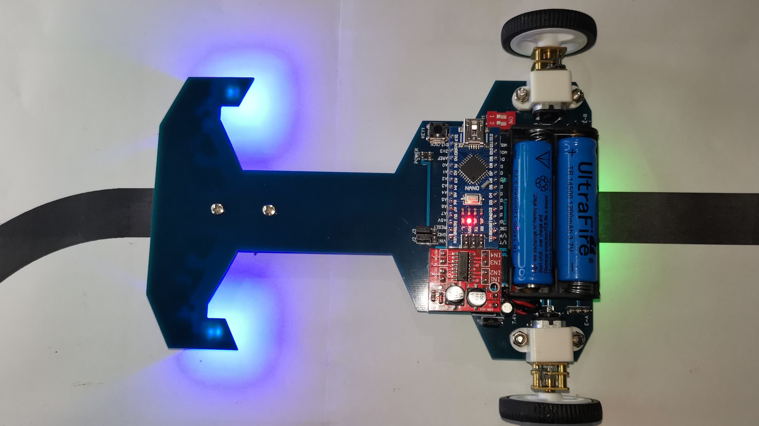
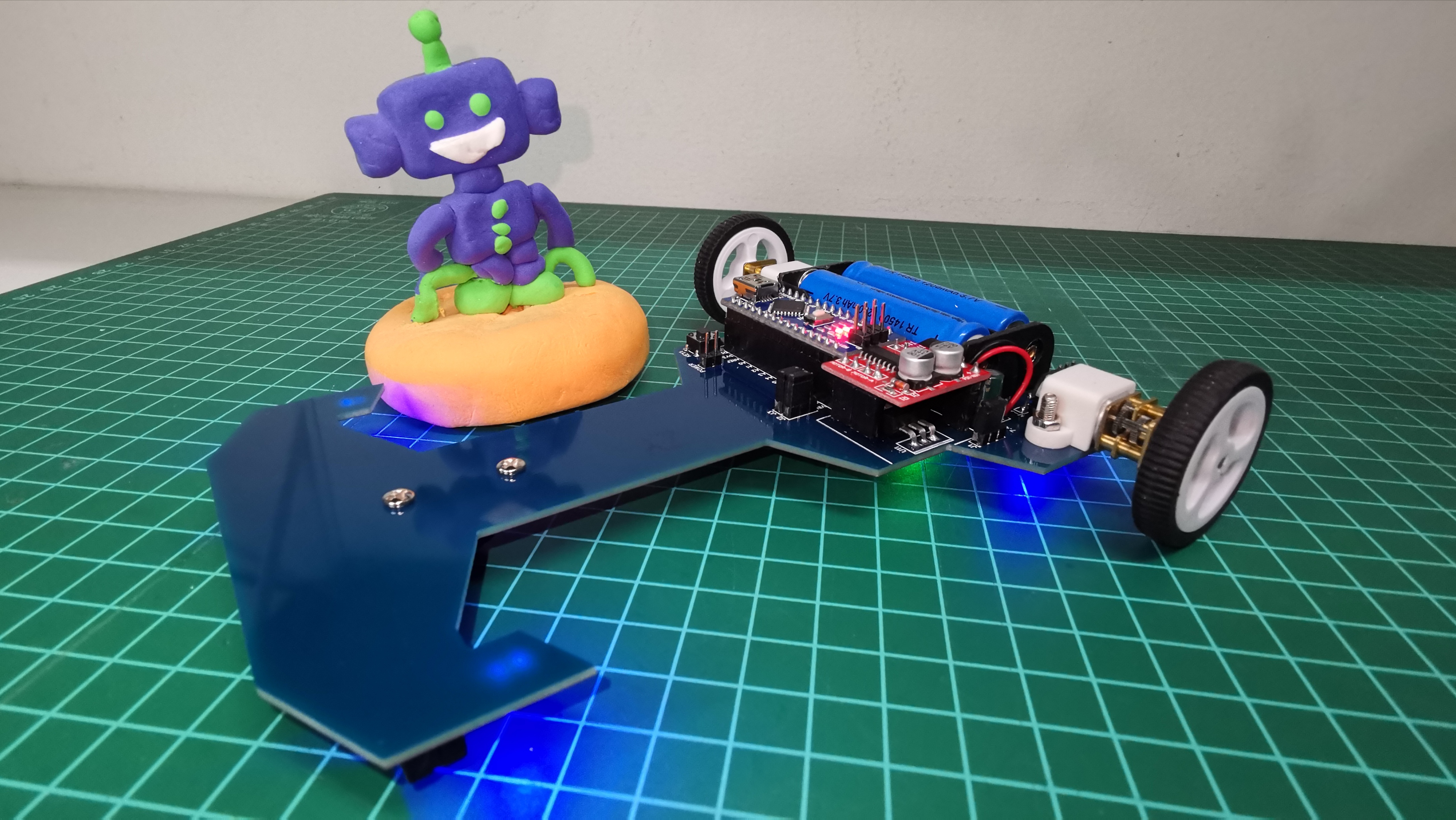
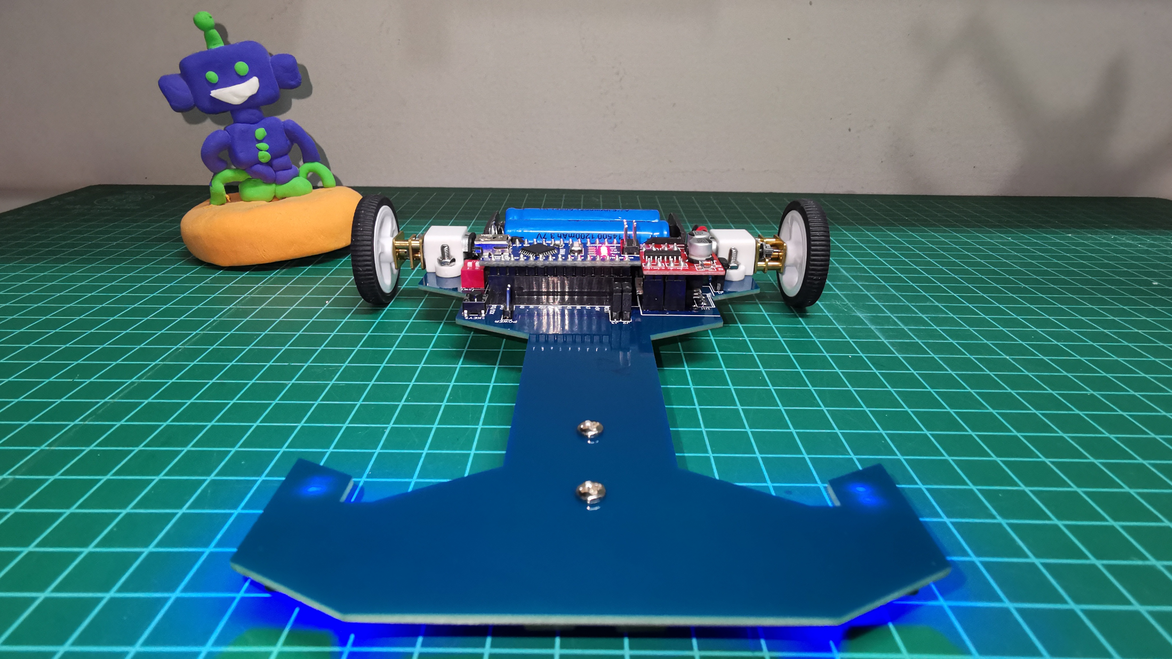
This is my second line follower robot (Version 4). Unlike the previous one, I have made the design of the printed circuit (Chassis).
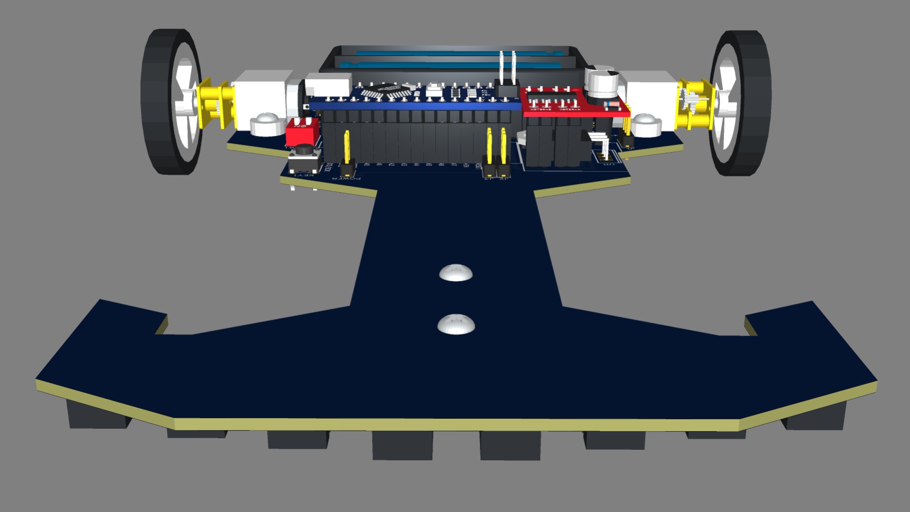
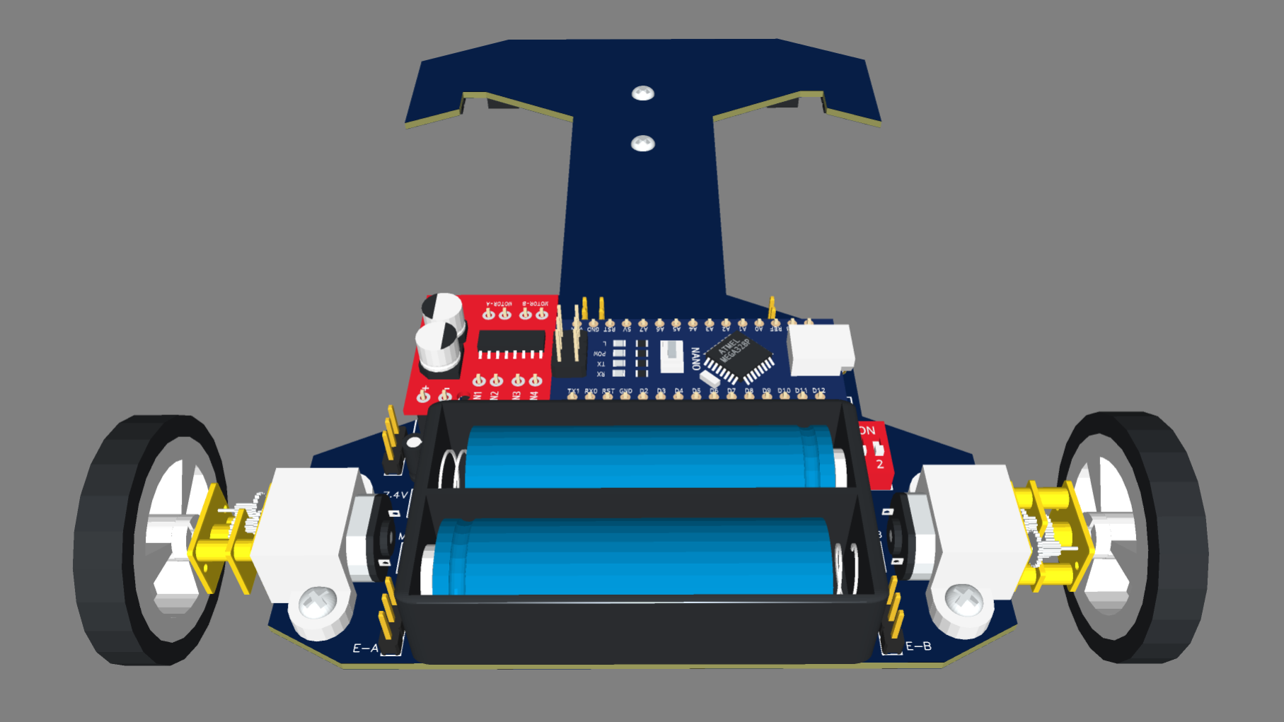
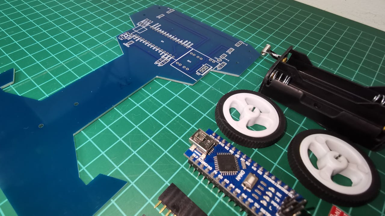
This is my second Line Follower Robot (Version 4). Unlike the previous one, I have made the design of the printed circuit using EasyEDA. This printed circuit acts as the chassis of the robot. The PCB manufacturing has been carried out by JLCPCB and I must say that they exceeded my expectations with impressive quality and shipment in record time.
The following video shows the final result of the prototype in which I have included the 3D models designed in Tinkercad.
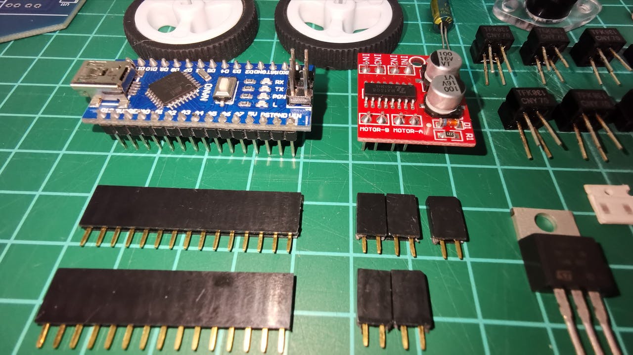
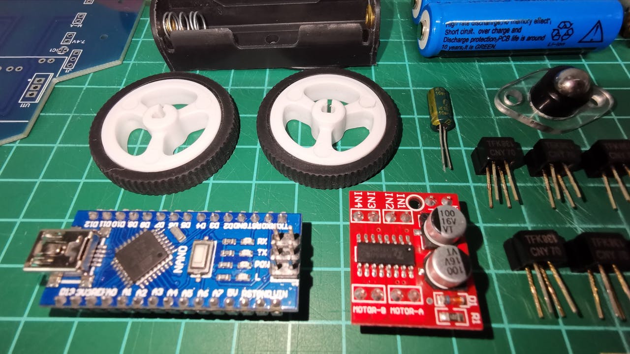
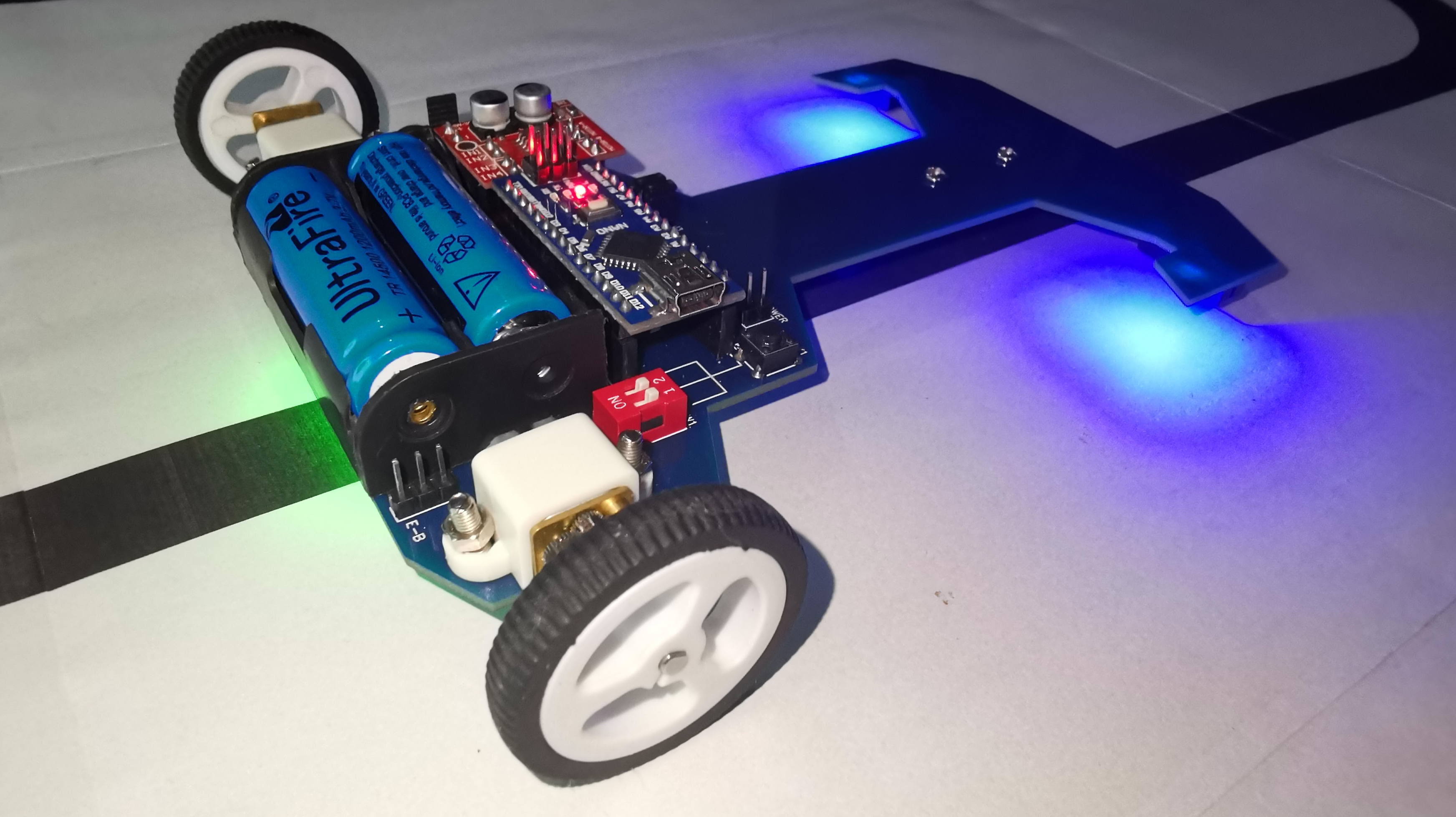
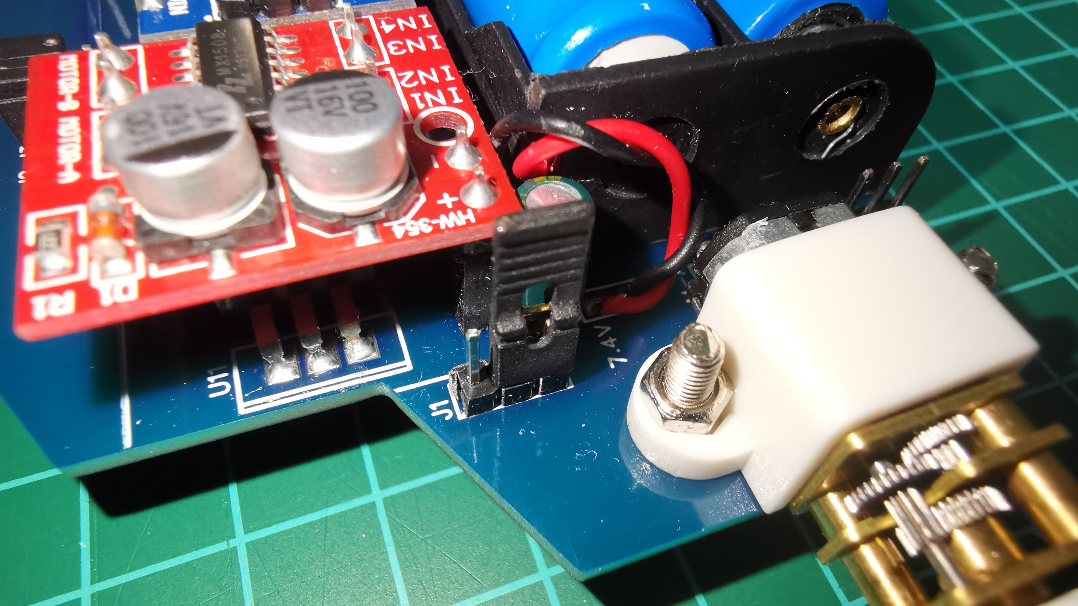
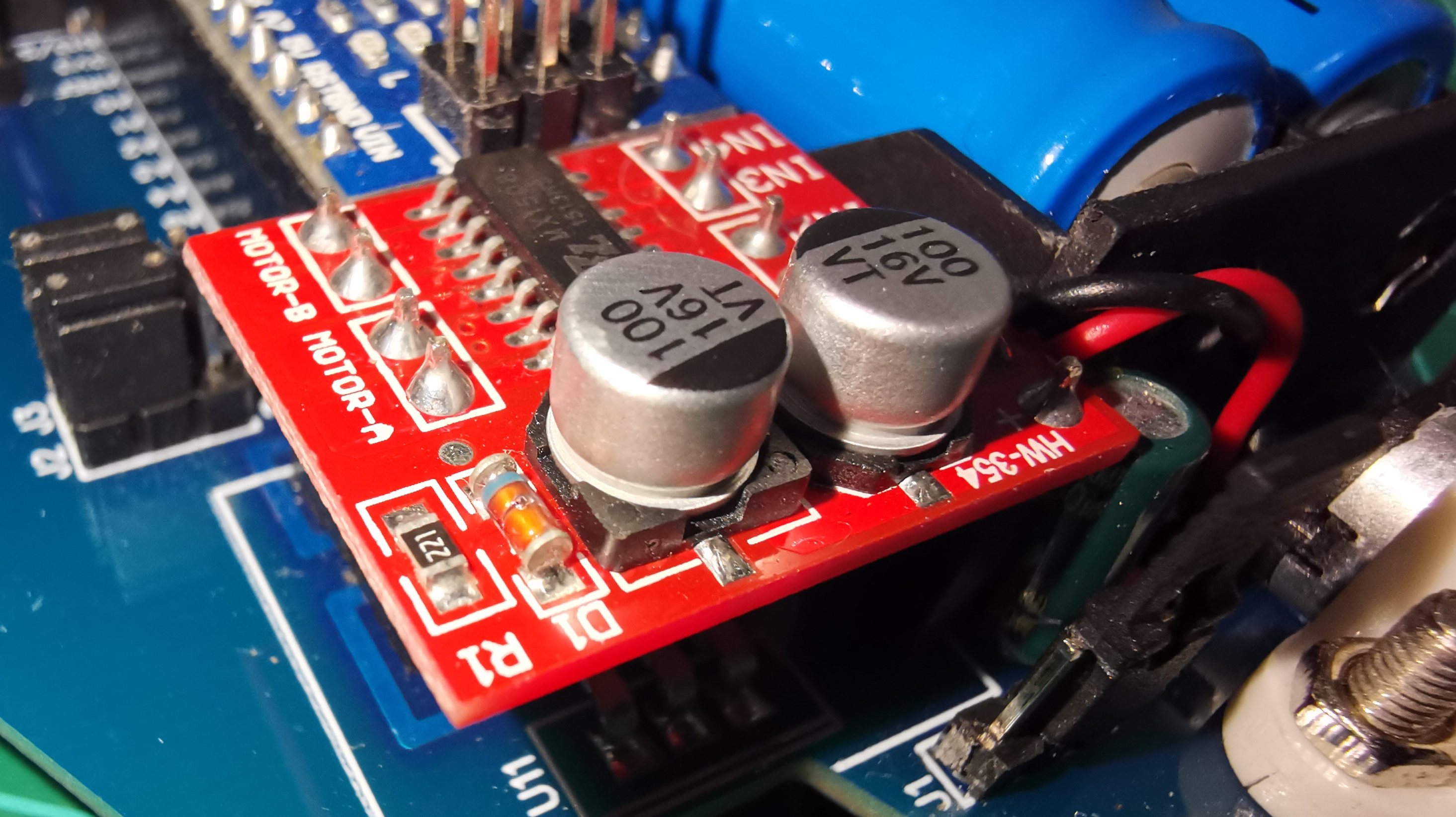
In the following video I show the tests carried out with the Mini Motor Driver (MX1508).
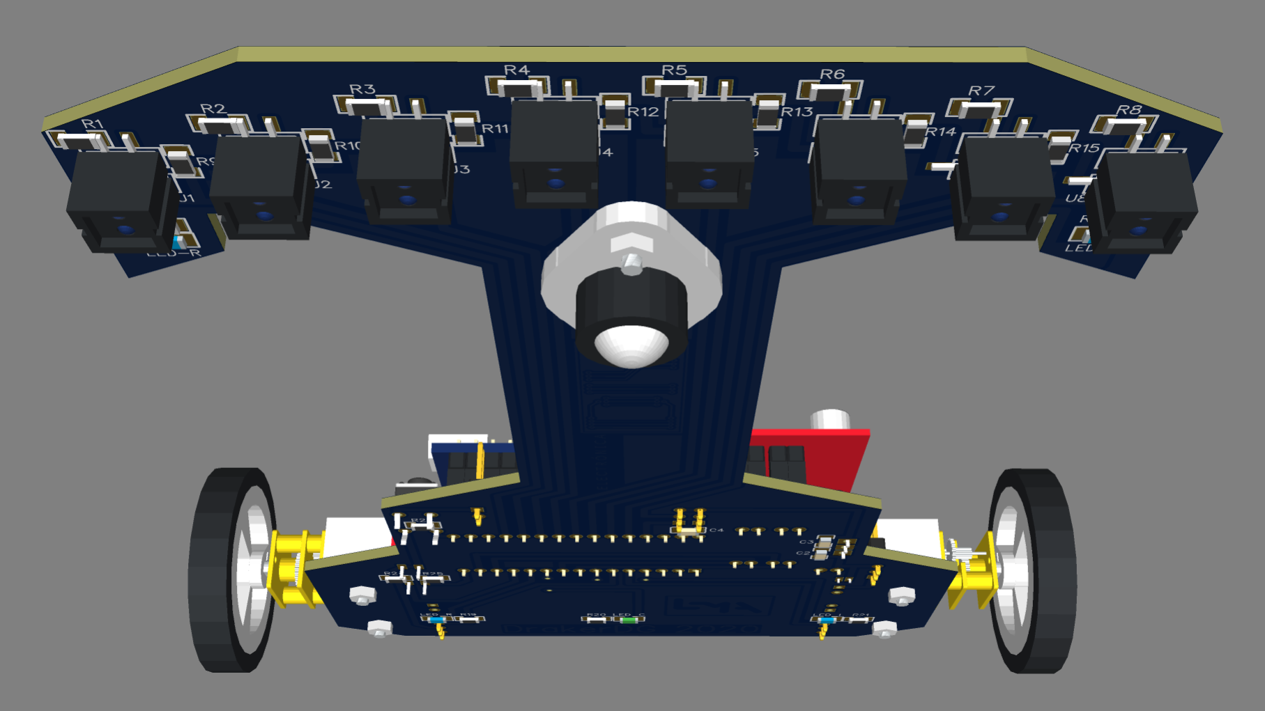
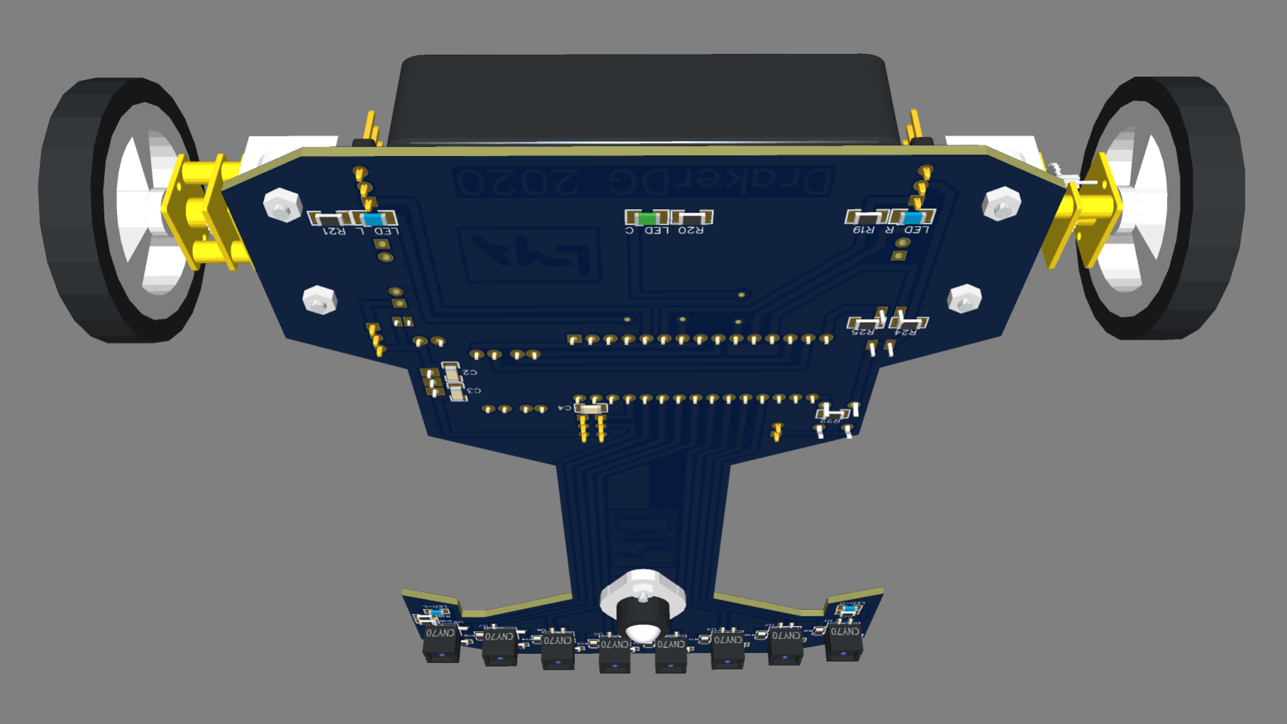
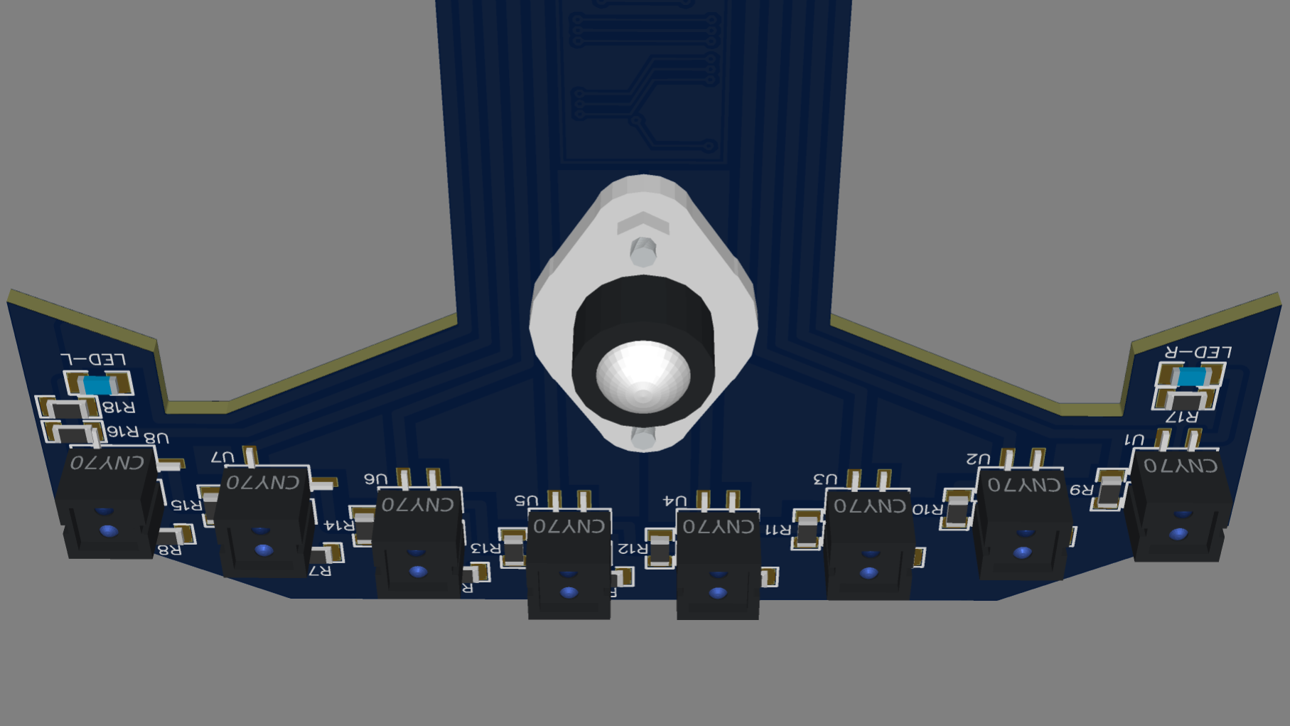
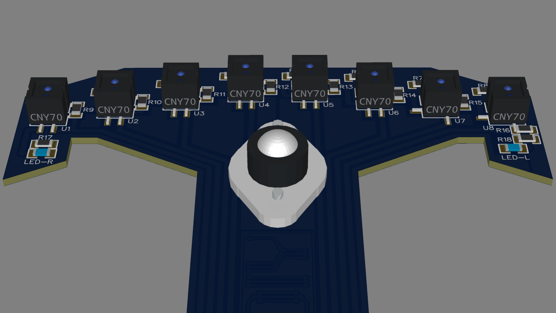
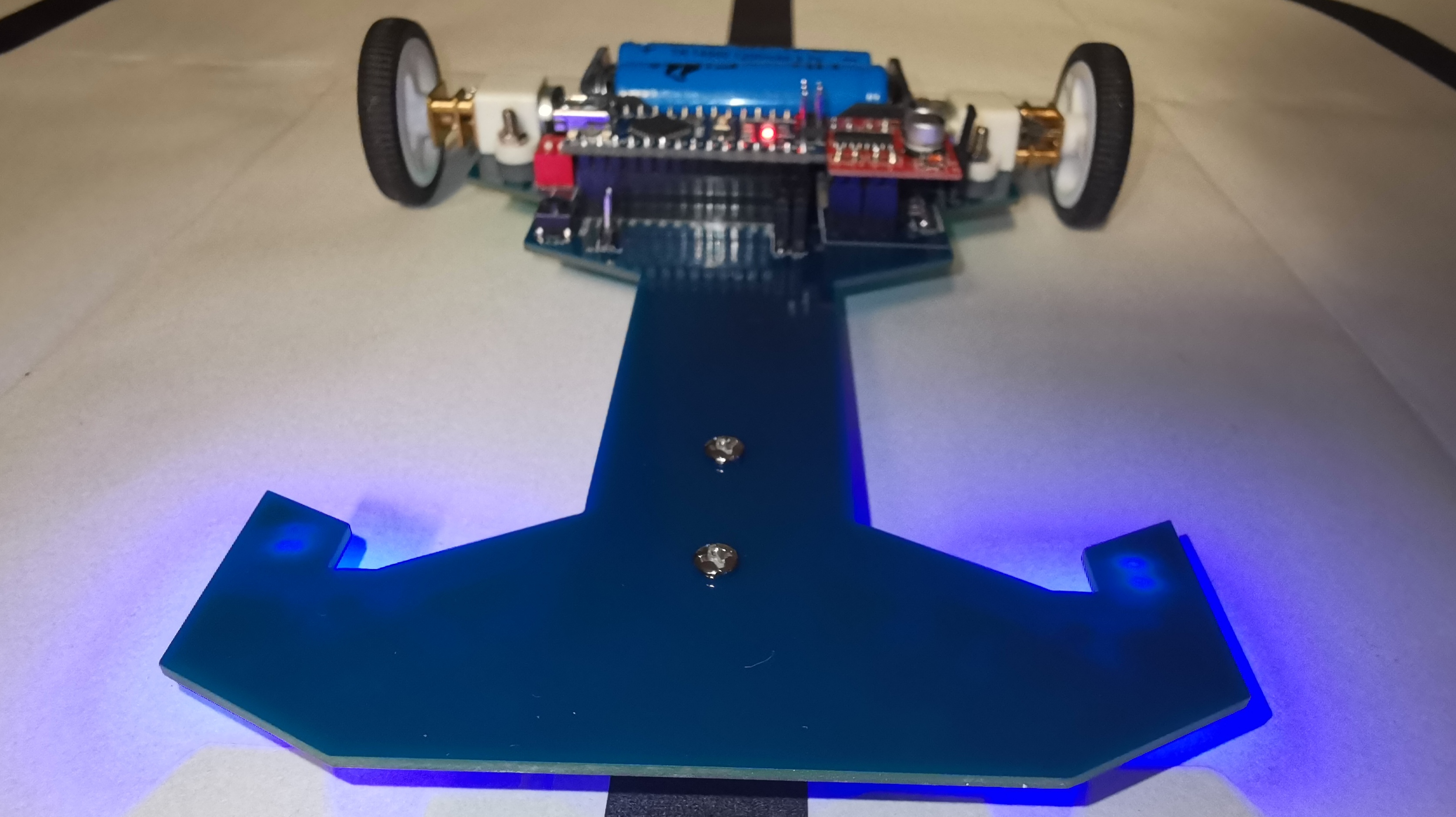
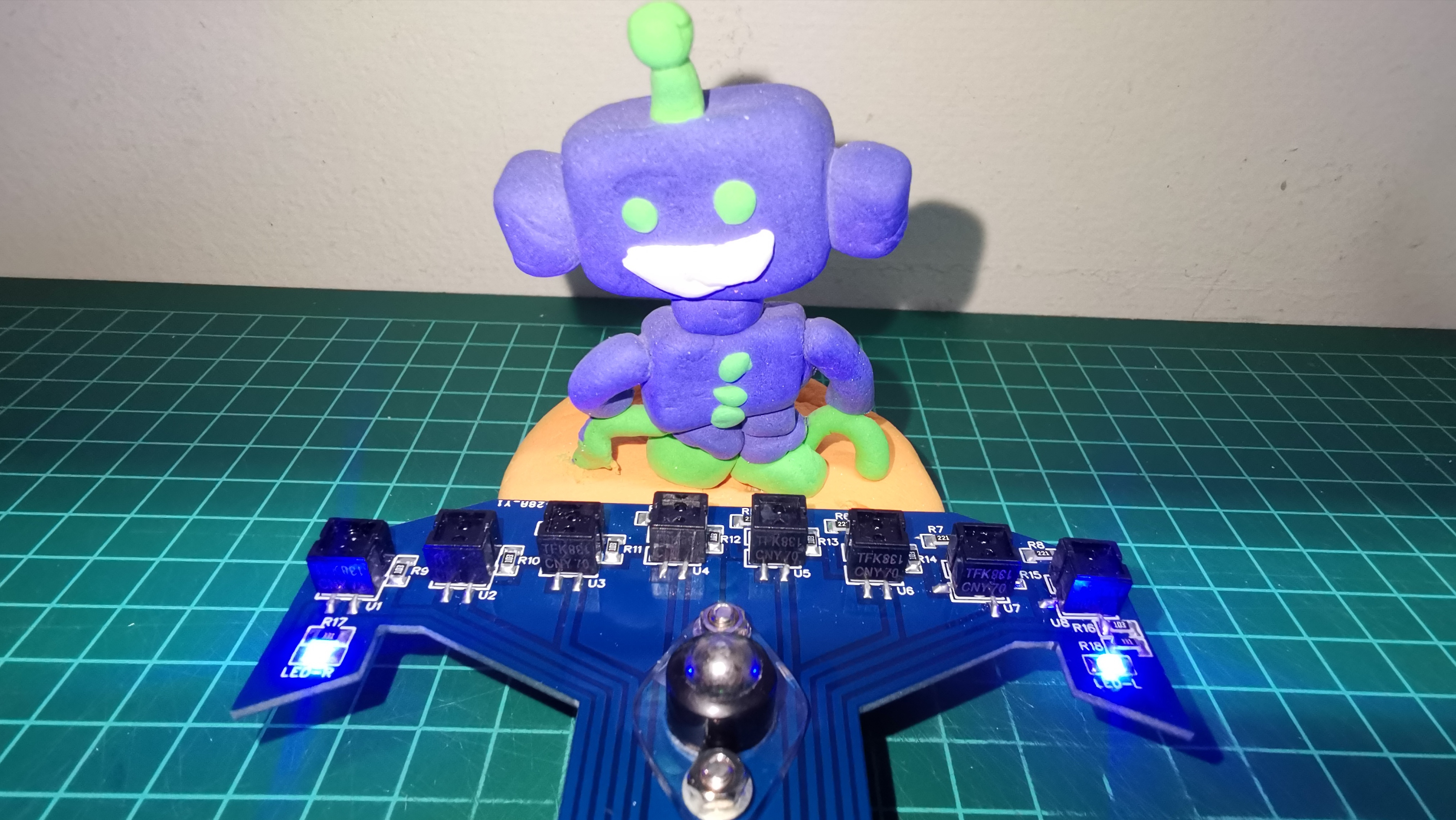
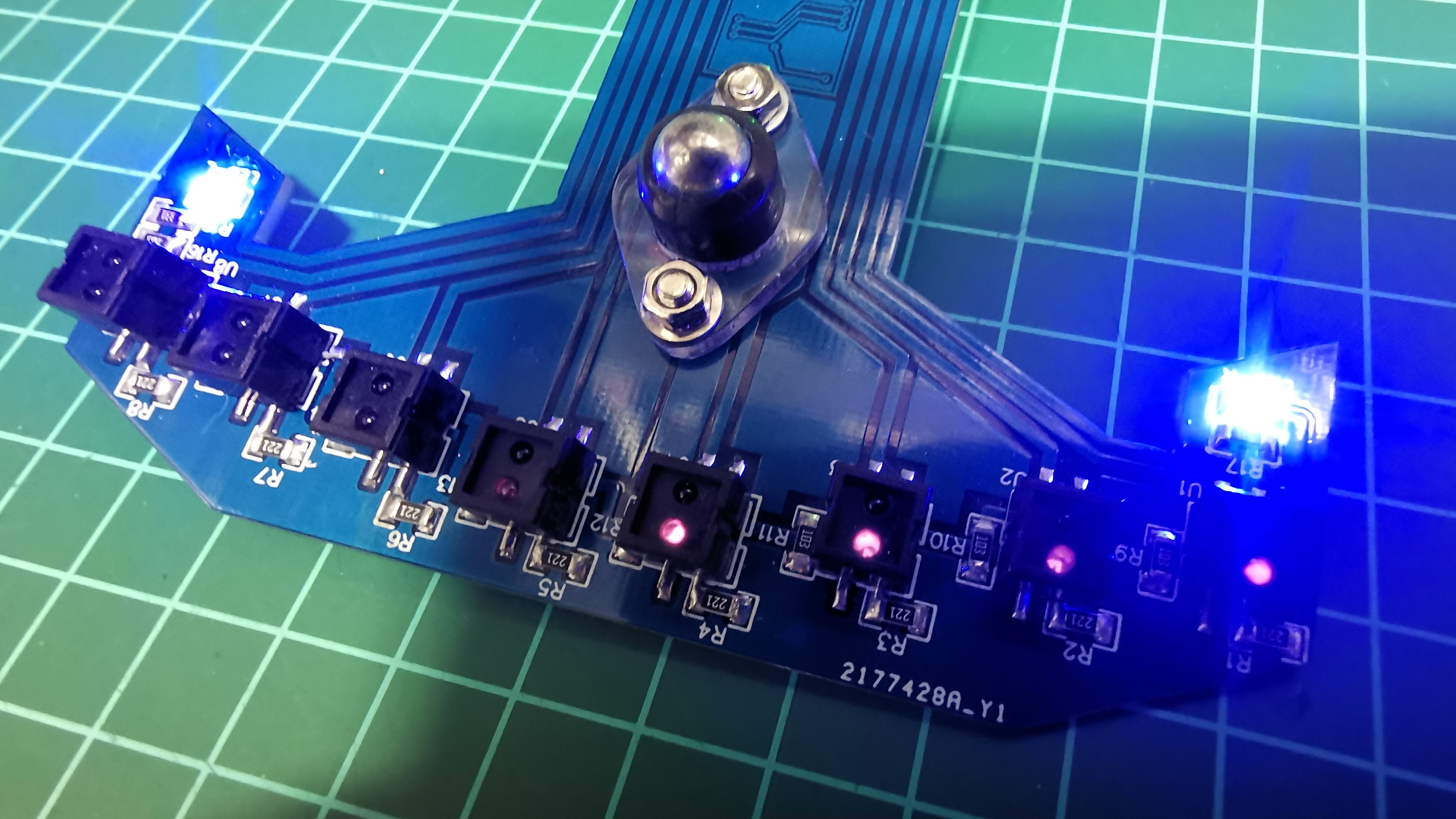
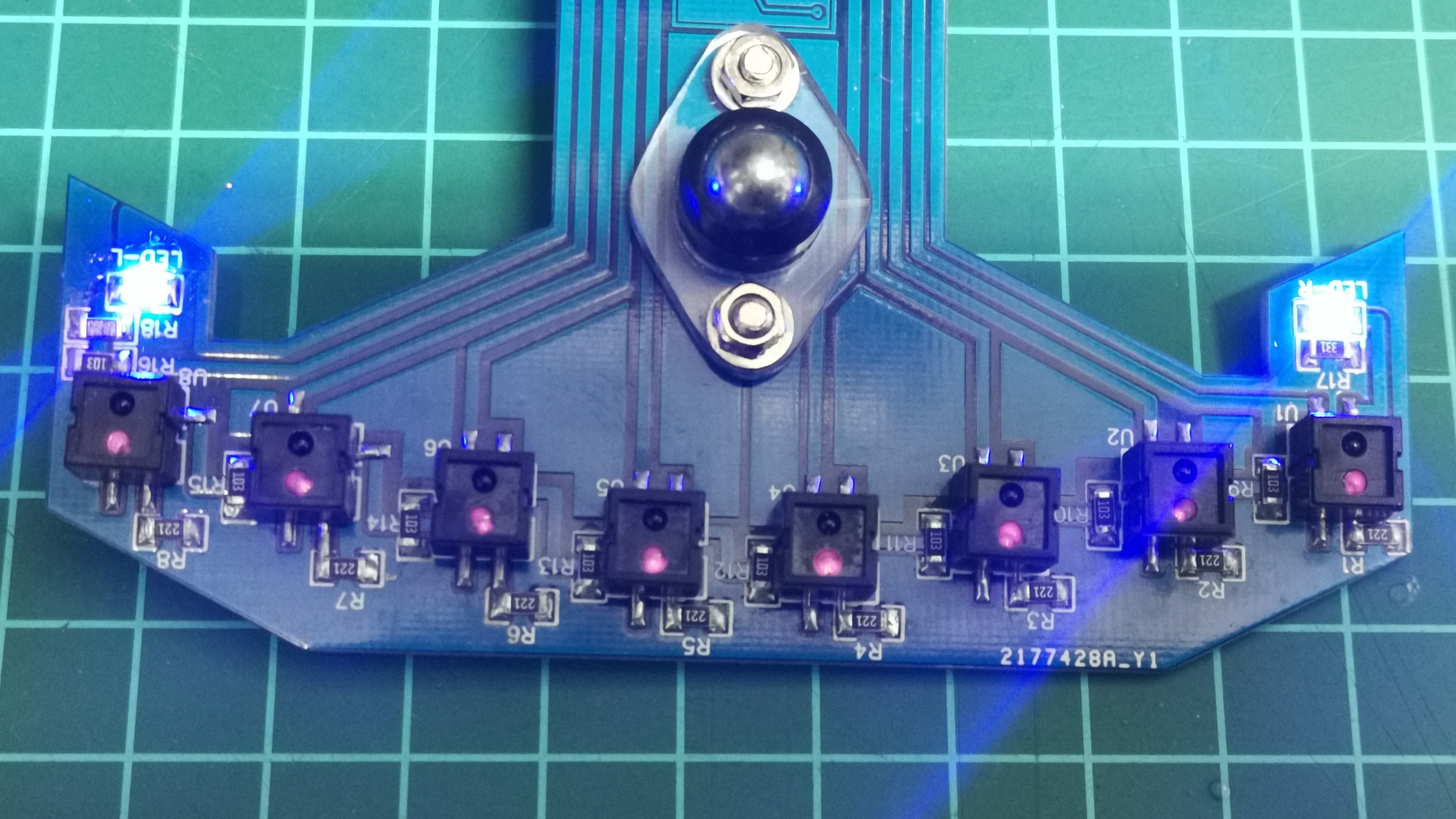
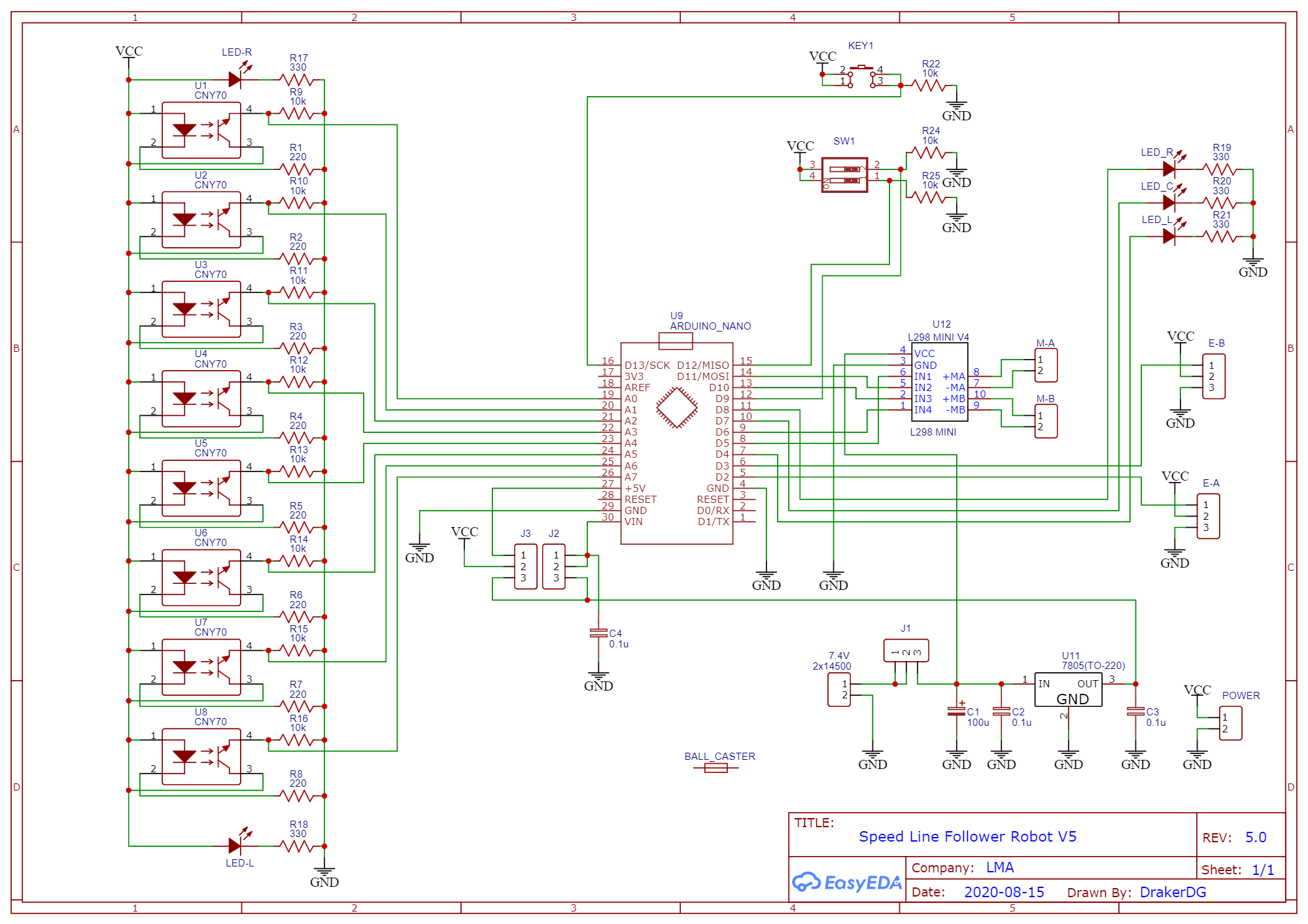
In the next video I show the tests with the 8 CNY70 sensors. These sensors are measured analogically, through ports A0 to A7 of the Arduino Nano. I use an initial algorithm to calibrate the sensors by normalizing the range from 0 to 1000, where 0 represents the white background and 1000 the black line. Upon completing the calibration, it enters the loop and starts the reading cycle, calculating the position from 0 to 7000, which represents the left sensor to the right sensor respectively. This position value is used to calculate the proportional error P. The range of P is -3500 (left) to 3500 (right), with 0 being the center value. The algorithm memorizes the value of the position of the last sensor (left or right) that detected the black line, this with the purpose of using this data for braking actions and line recovery.
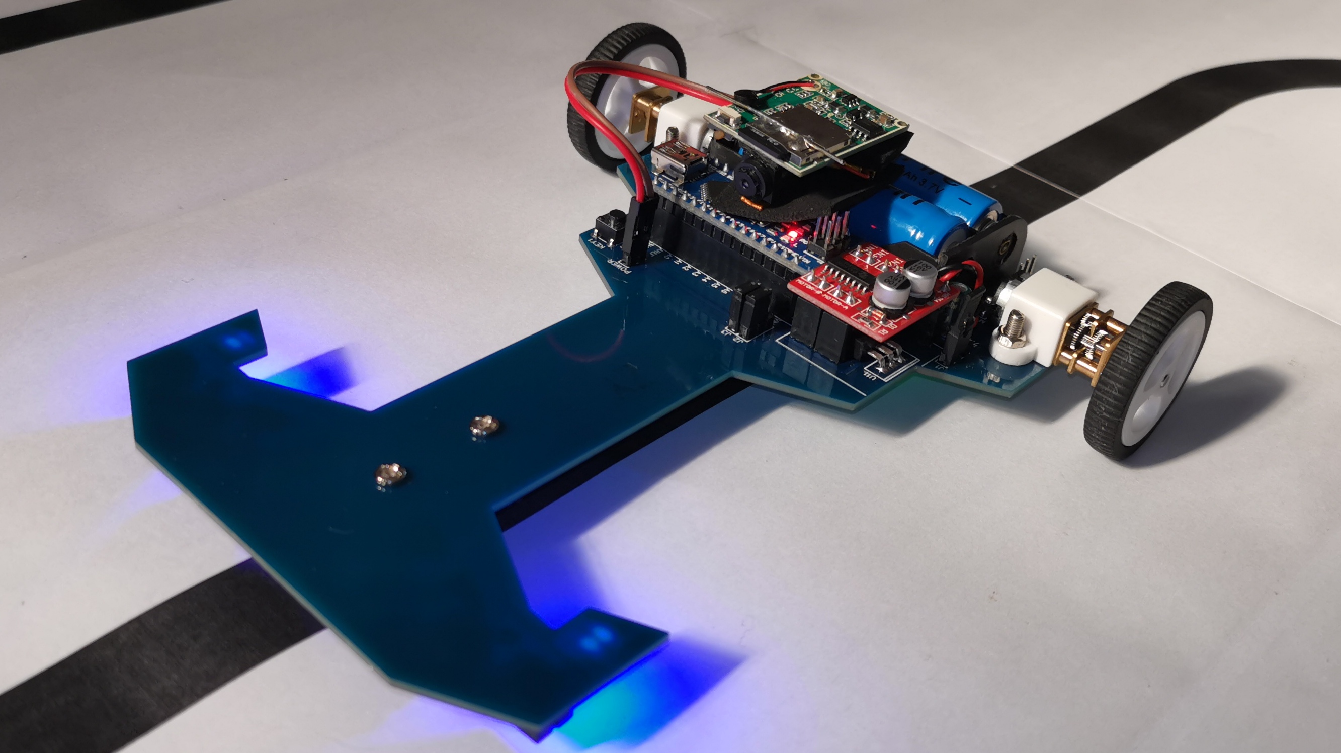
The final test with the circuit 95% mounted, is shown in the following video. A last amperage test having a maximum consumption of 200mA.
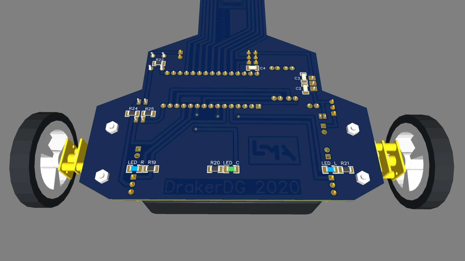
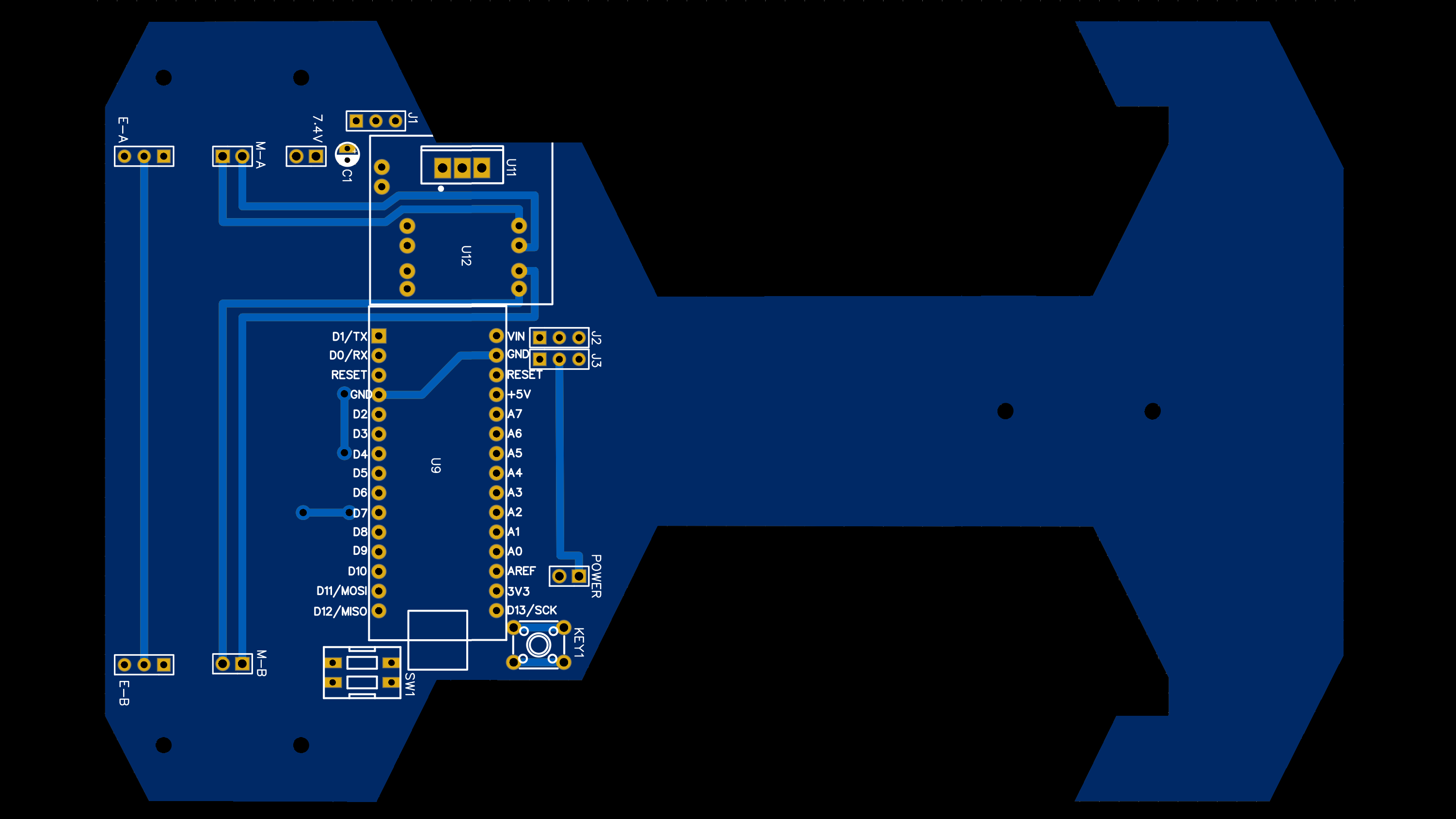
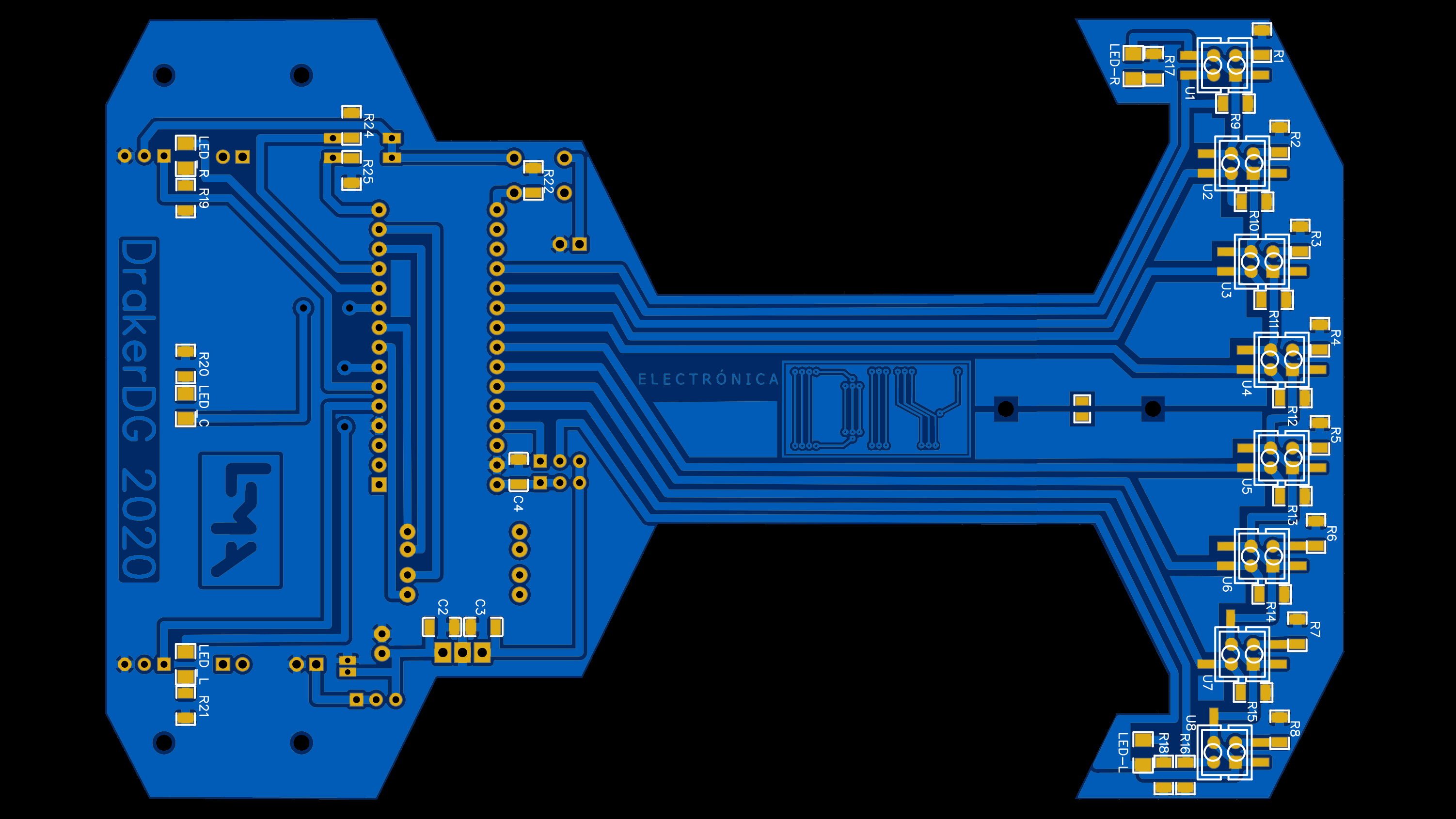
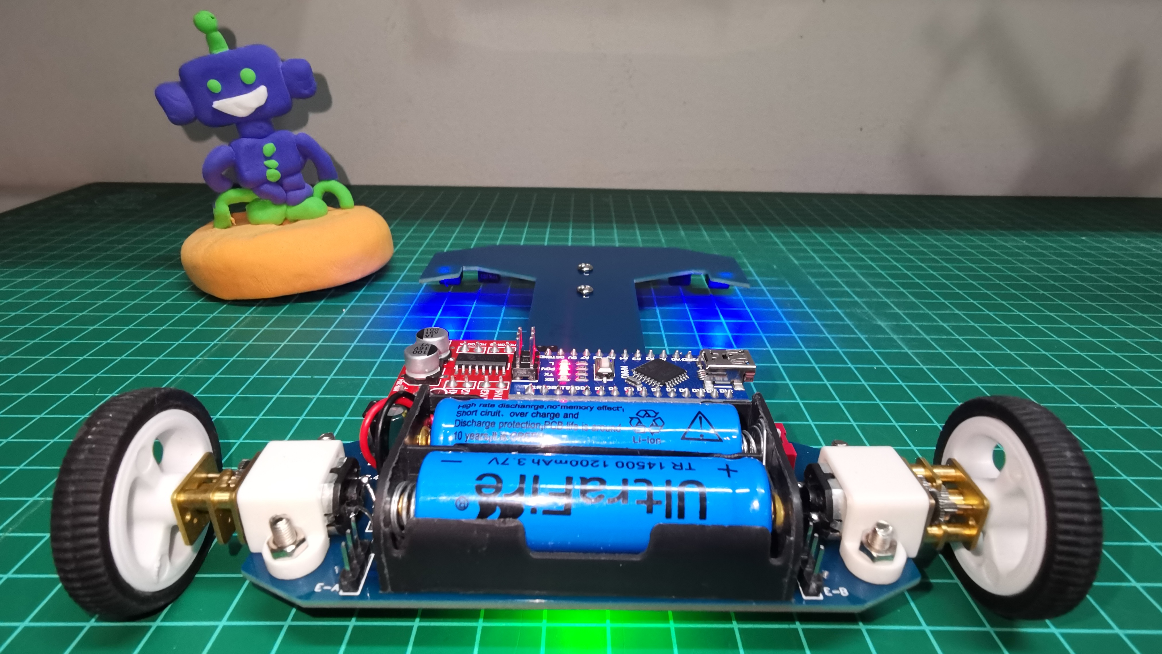
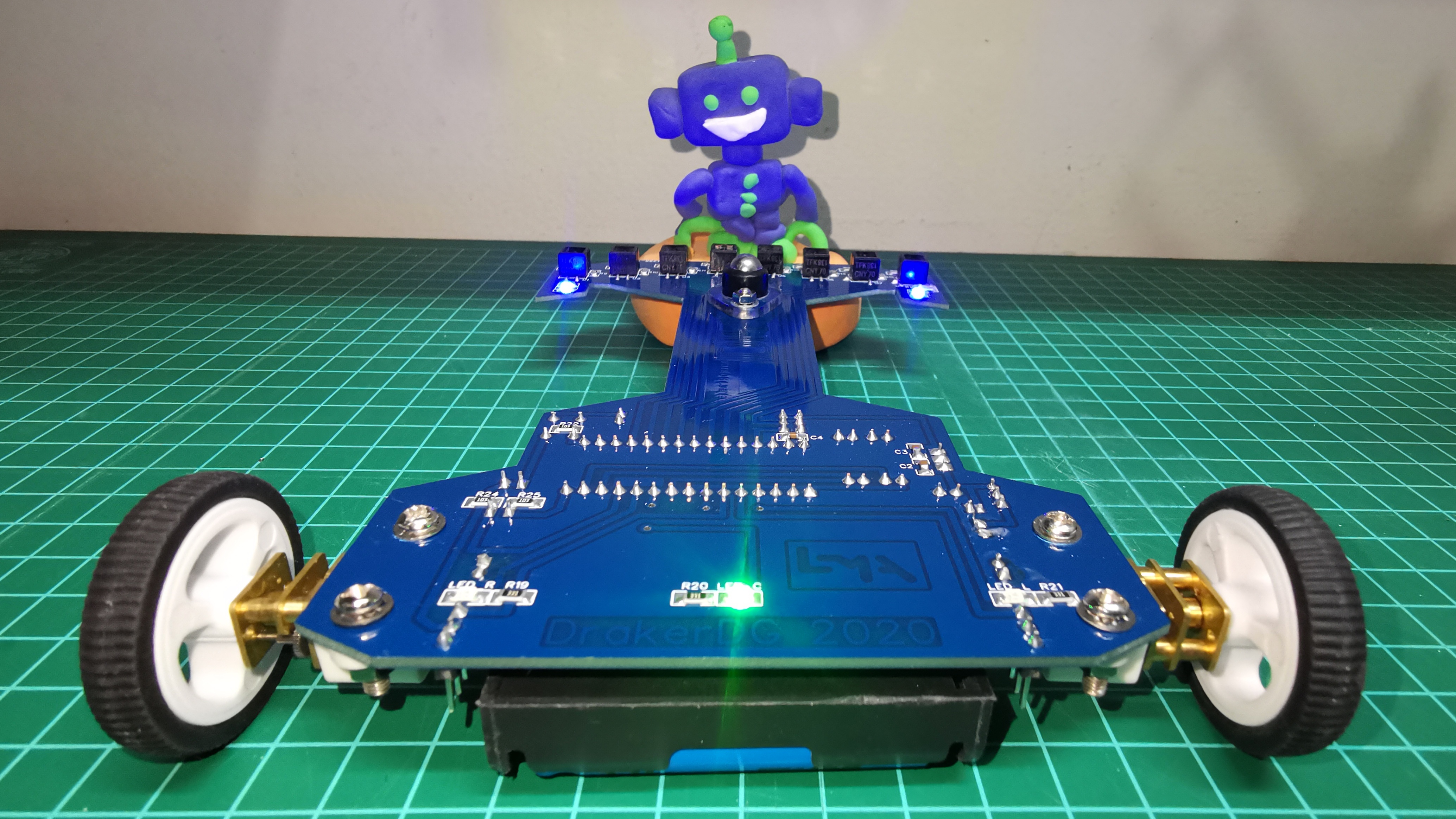
This is the latest version of the robot’s printed circuit, ready to be manufactured on JLCPCB.
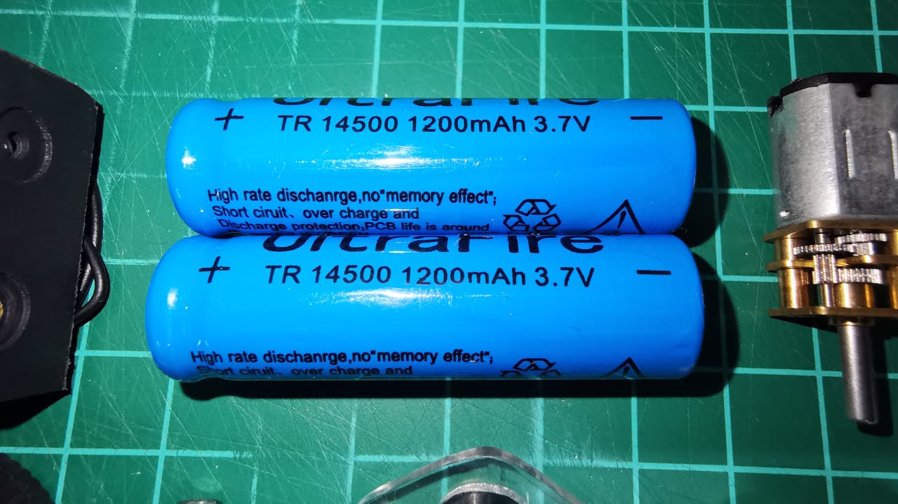
This is the unboxing.
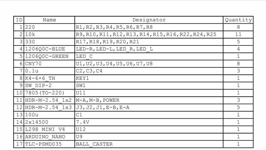
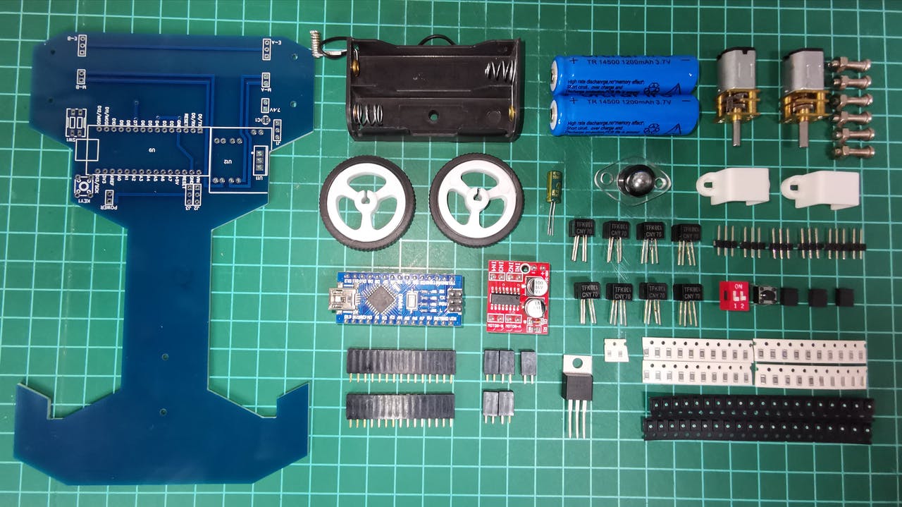
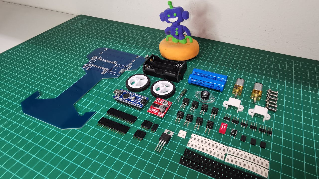
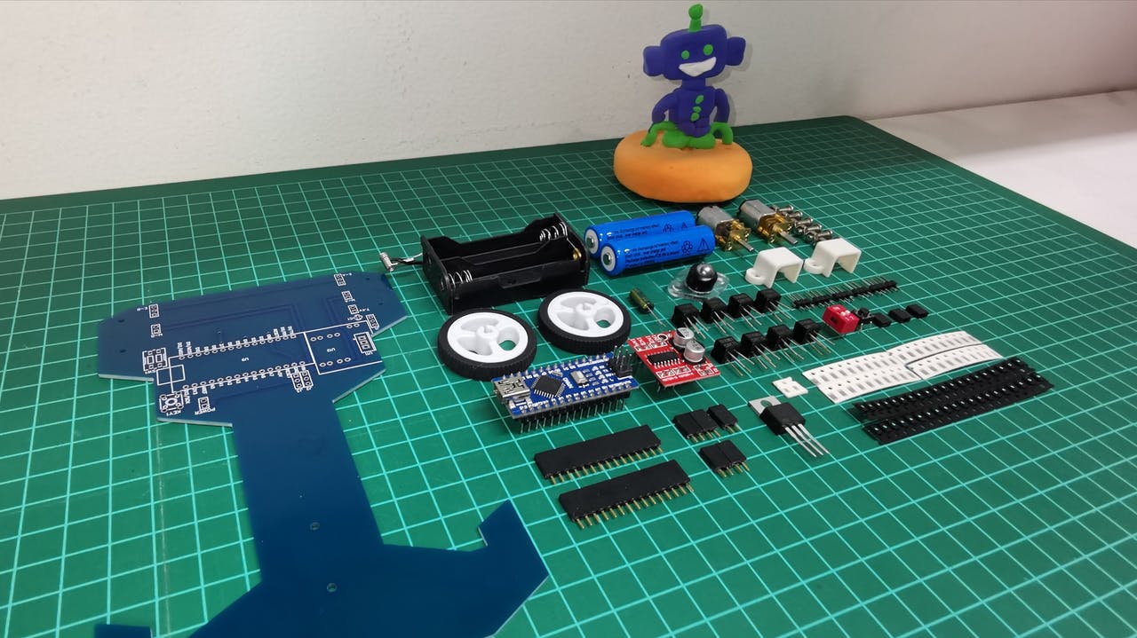
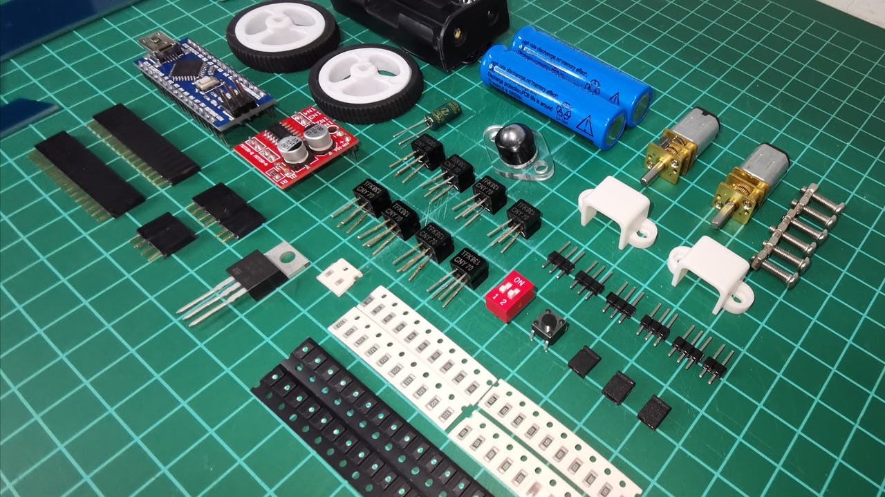
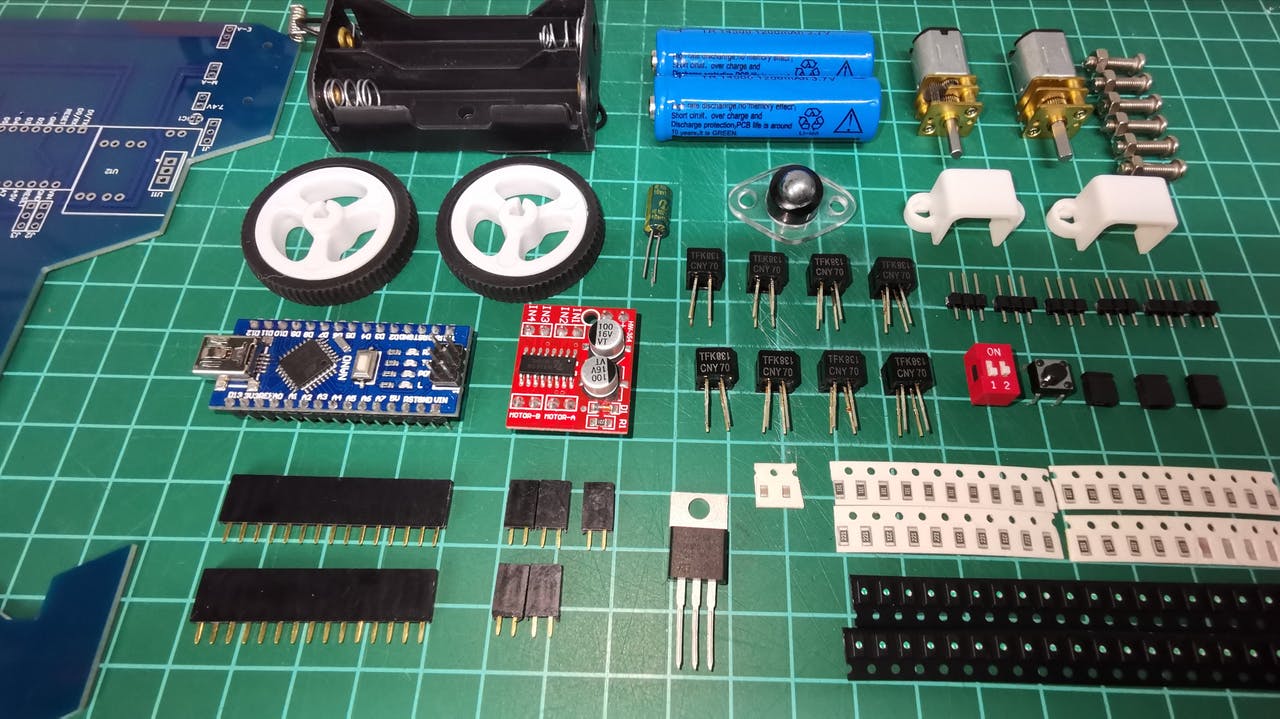
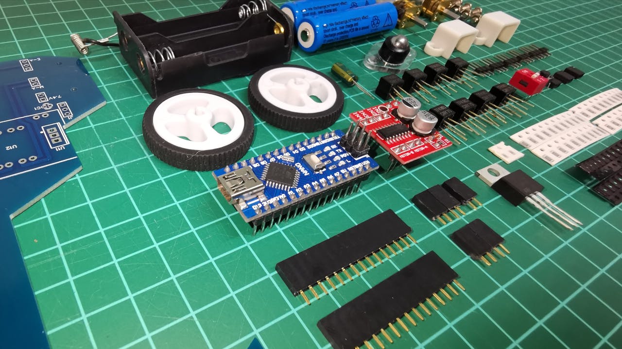
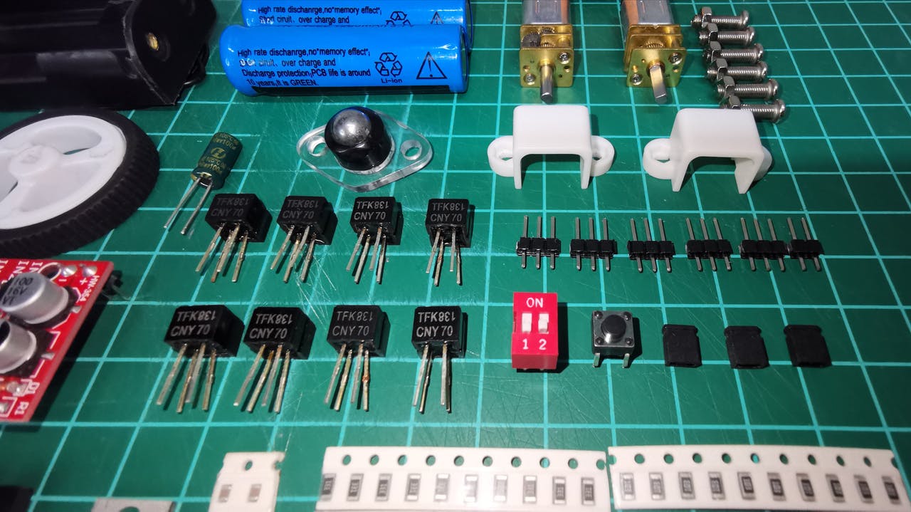
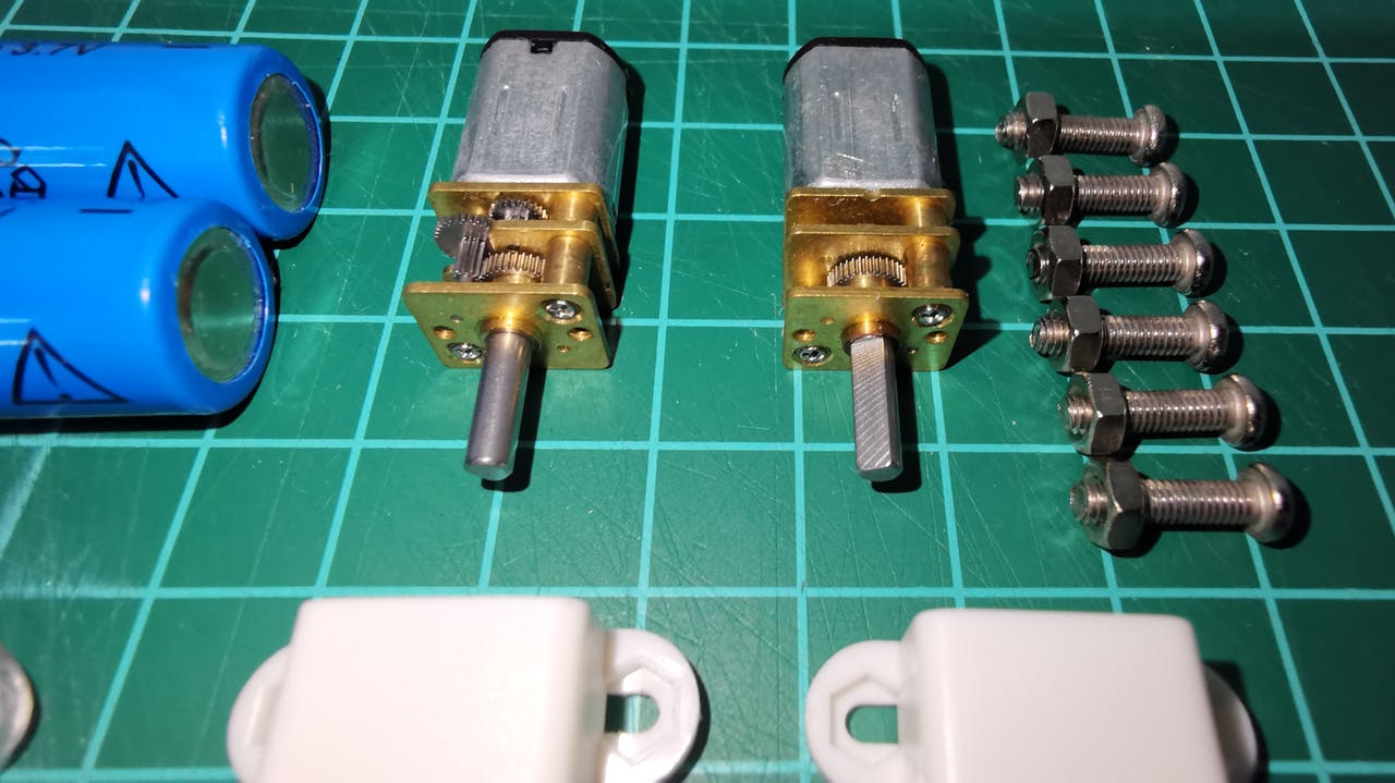

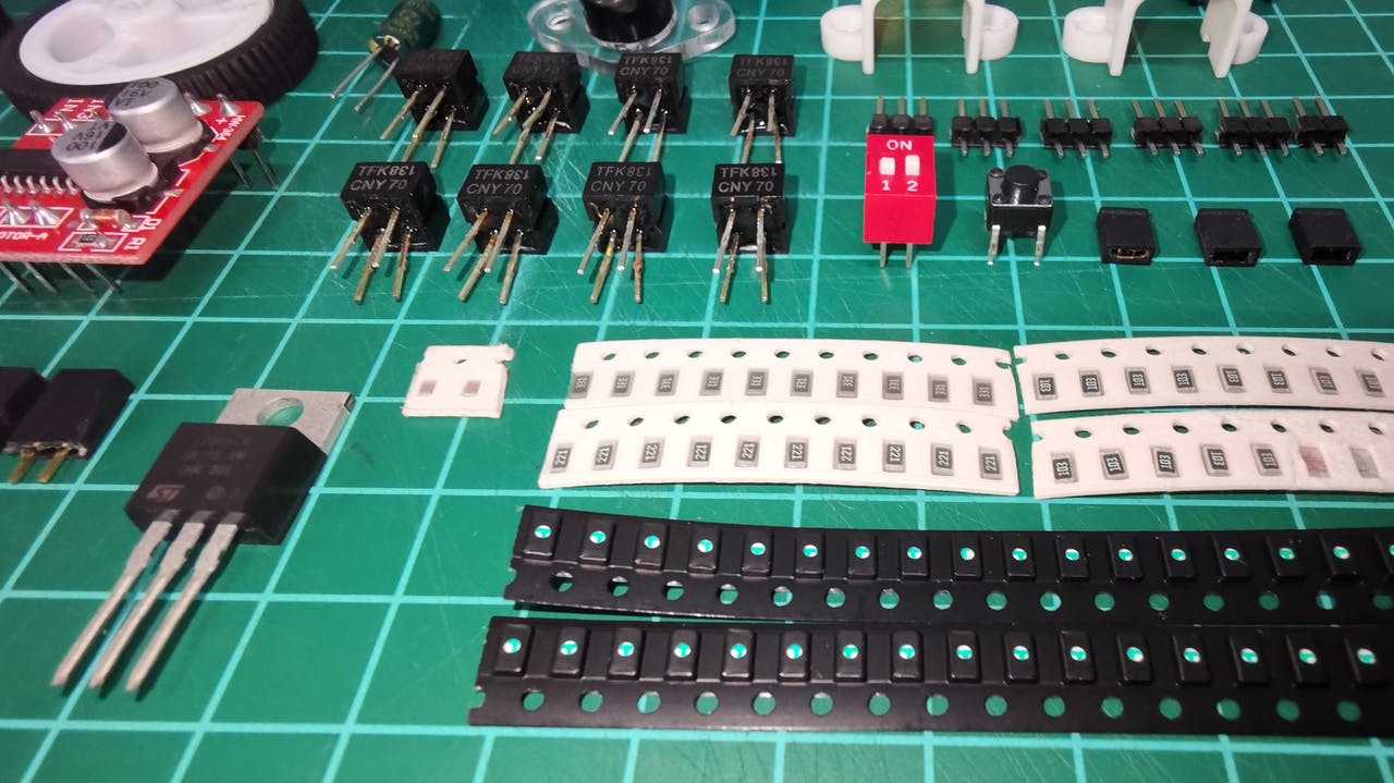
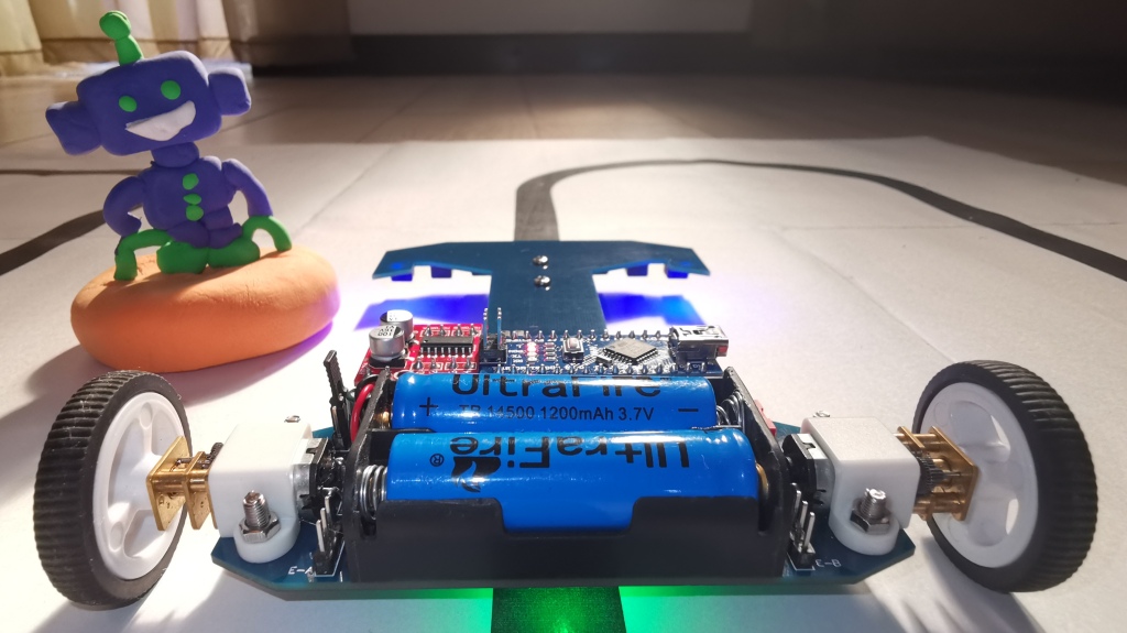
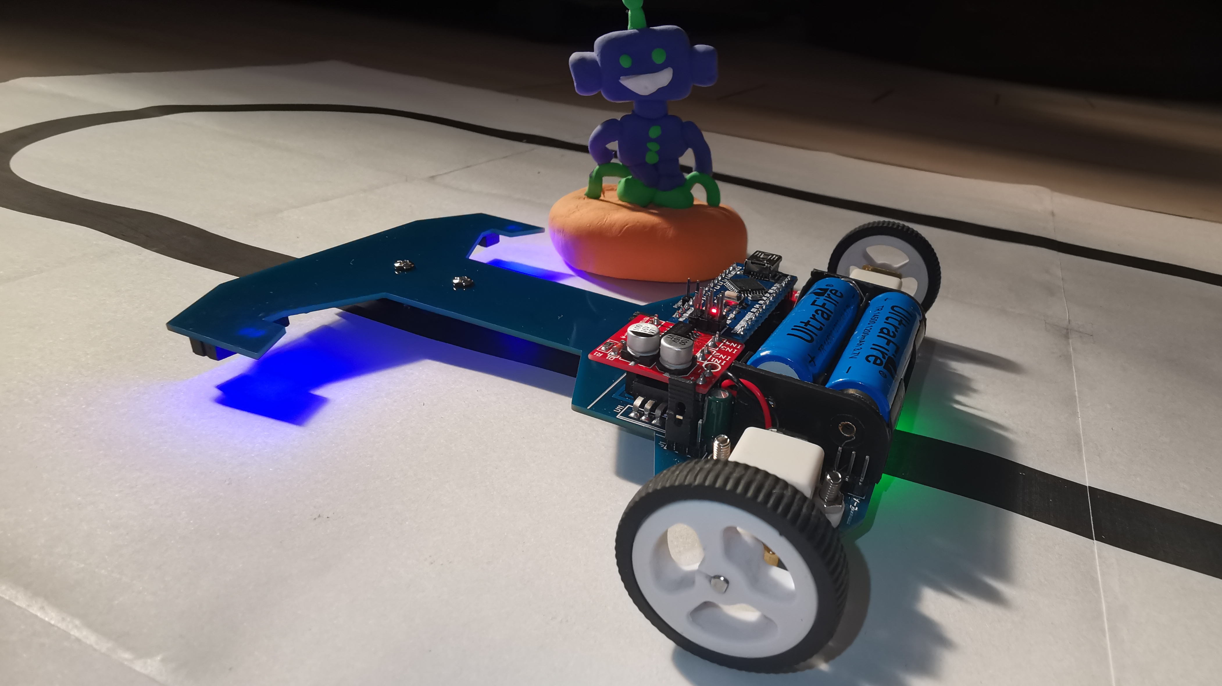
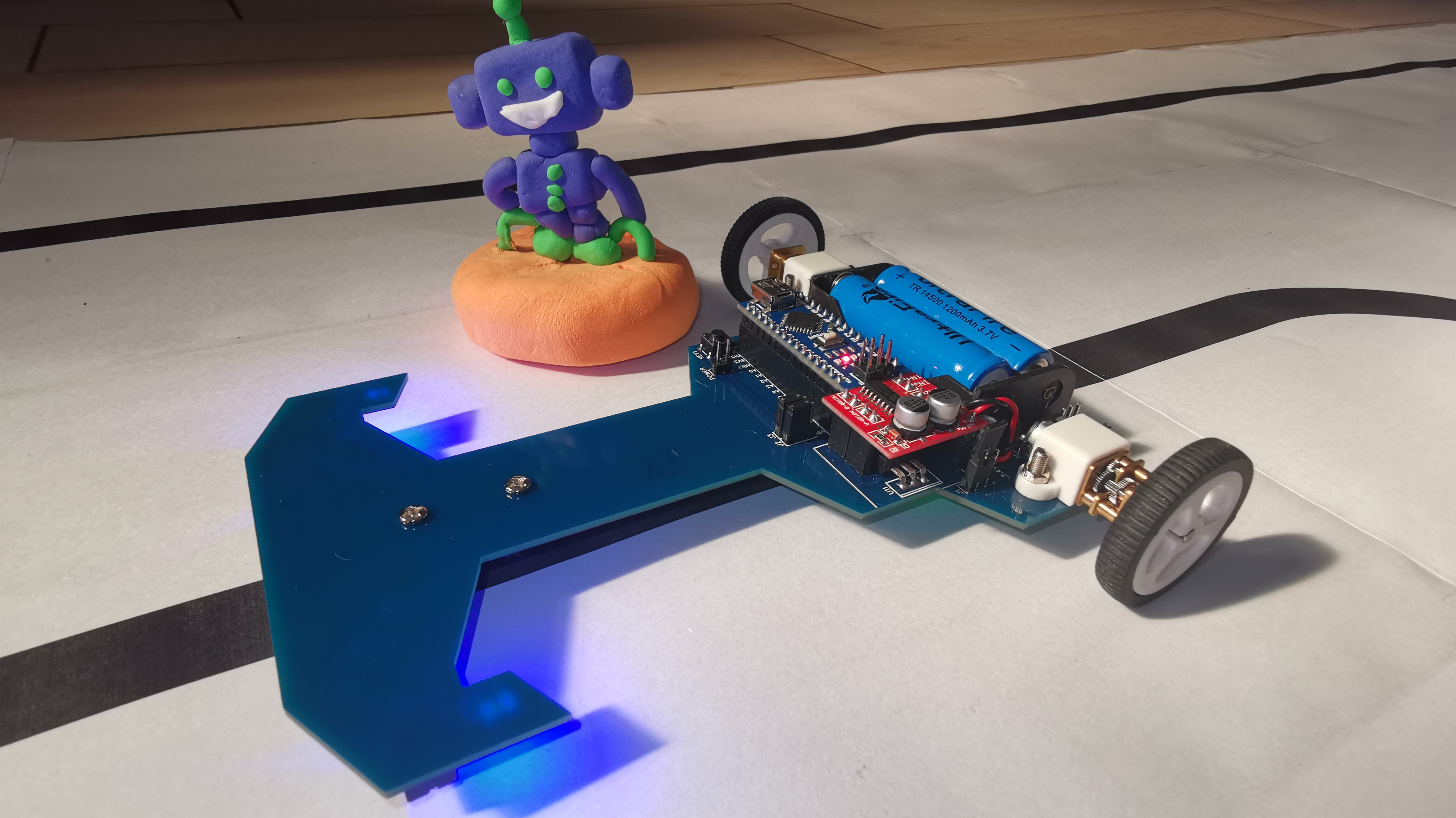
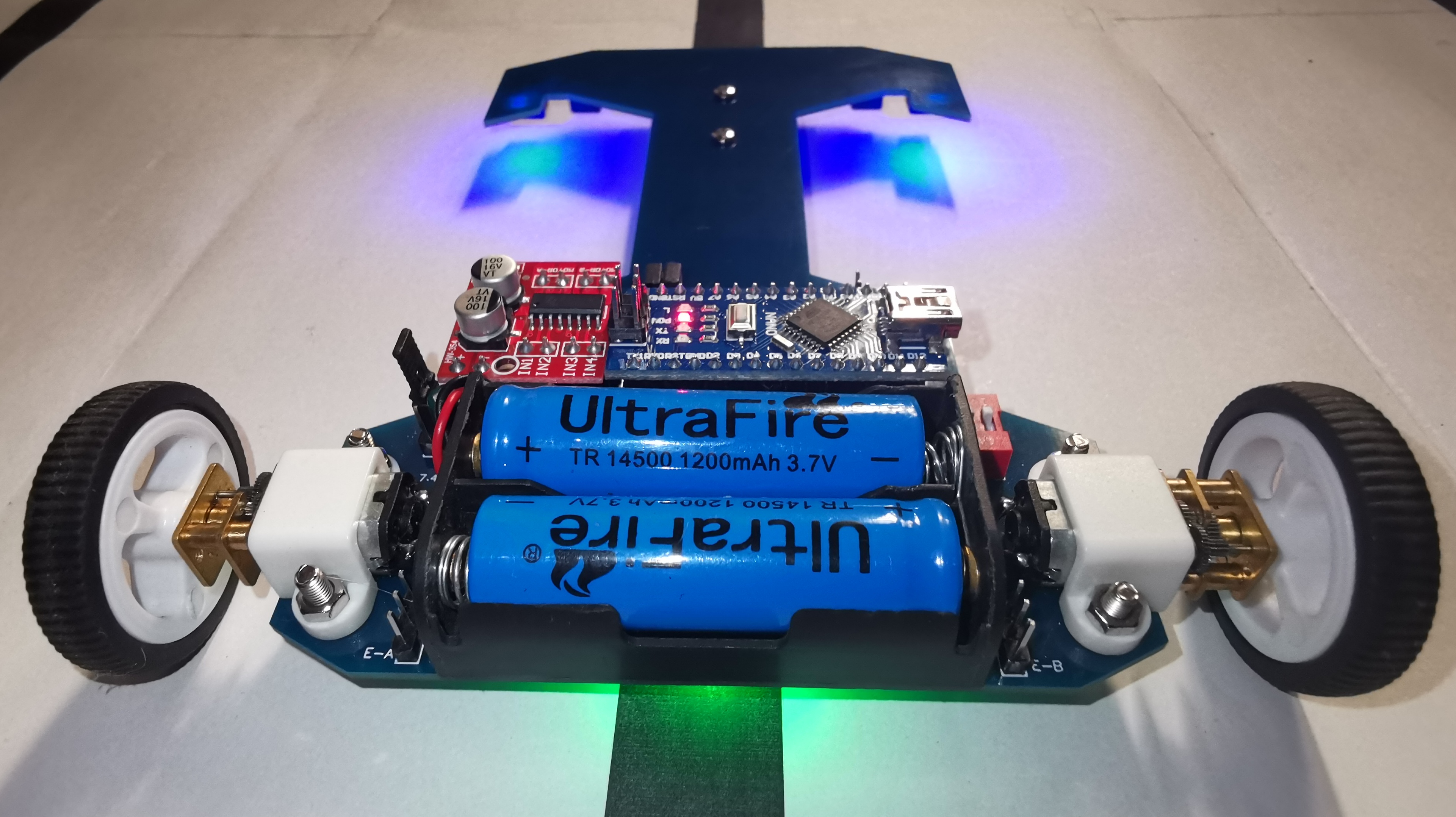
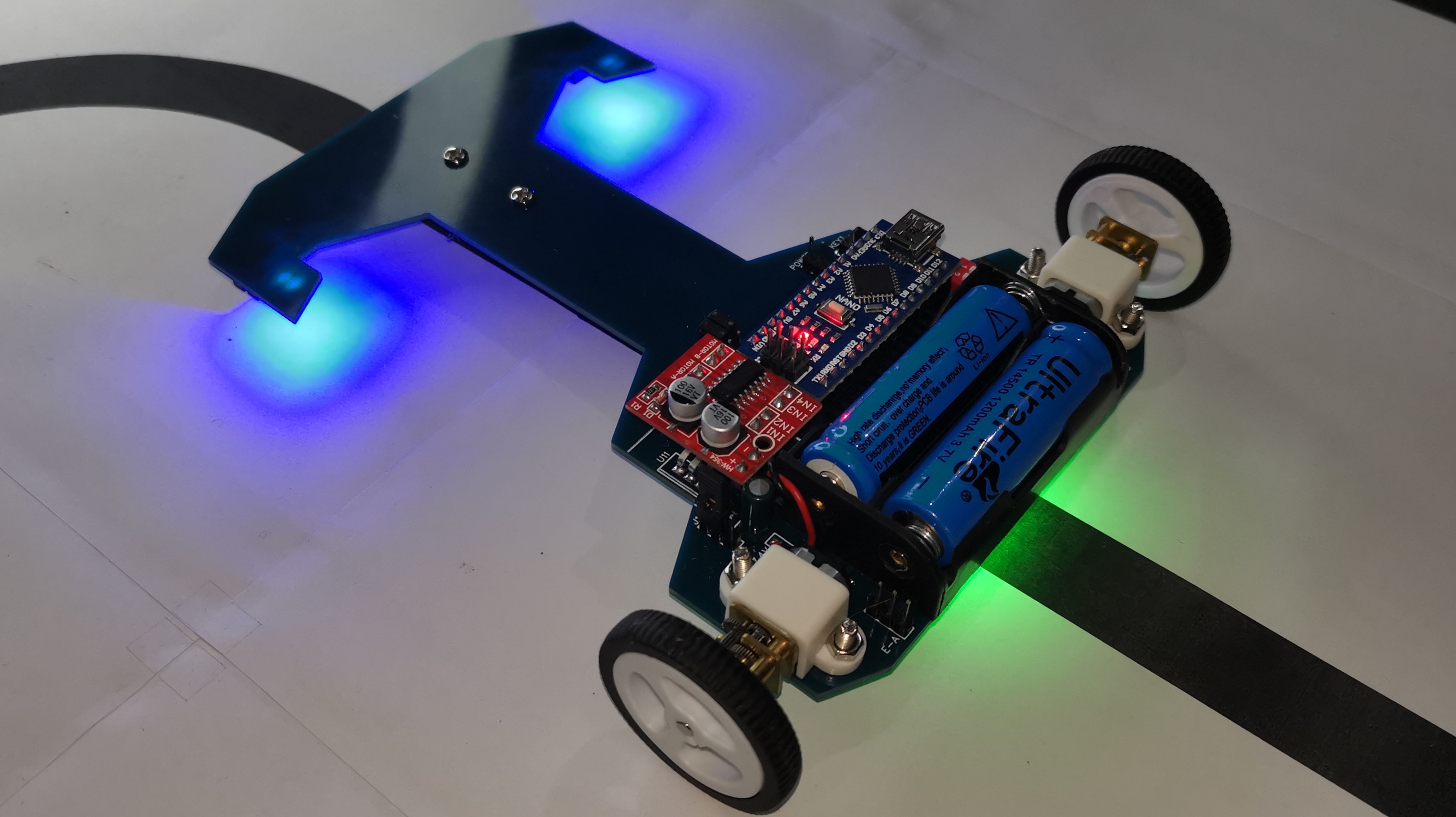
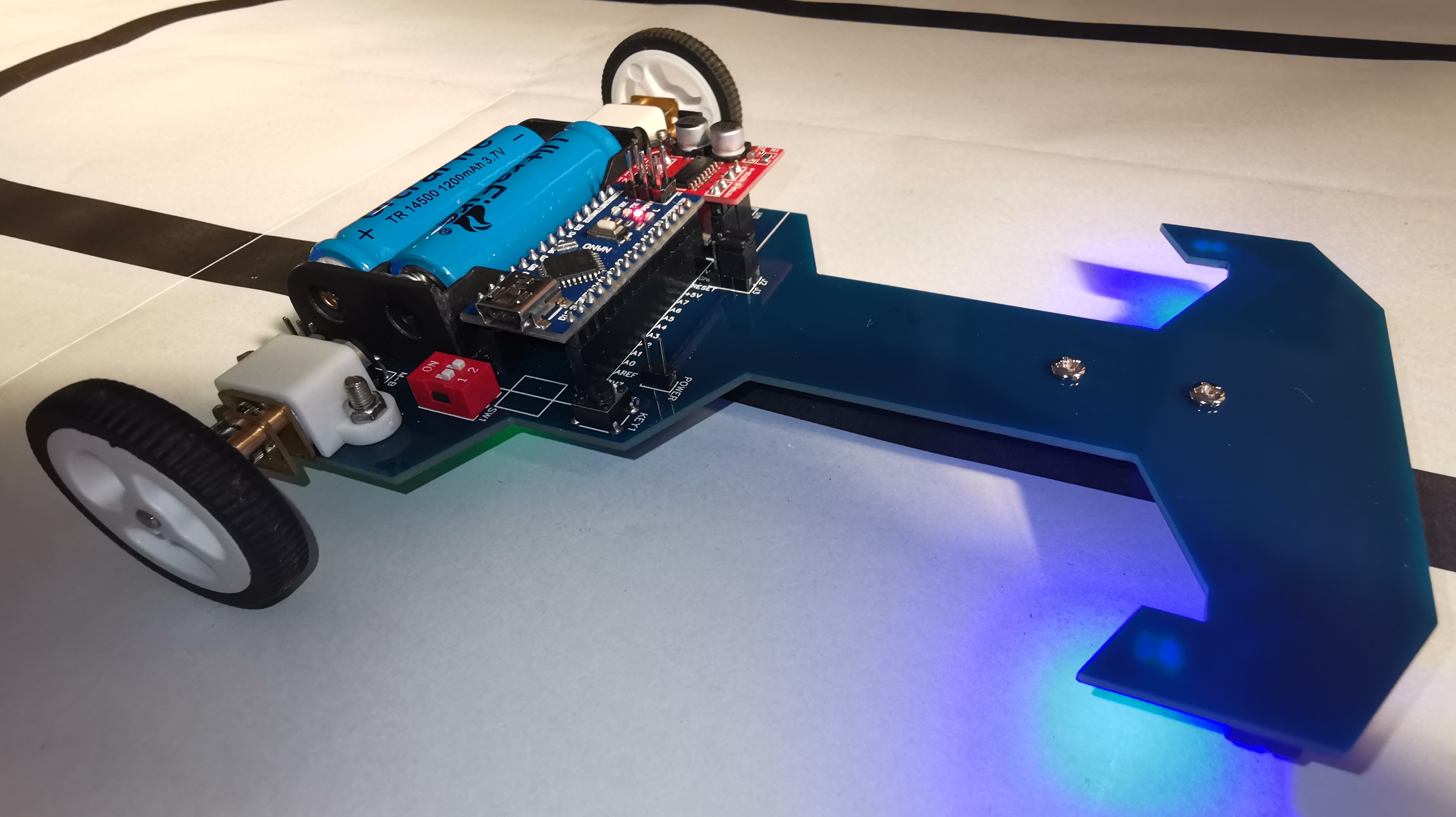
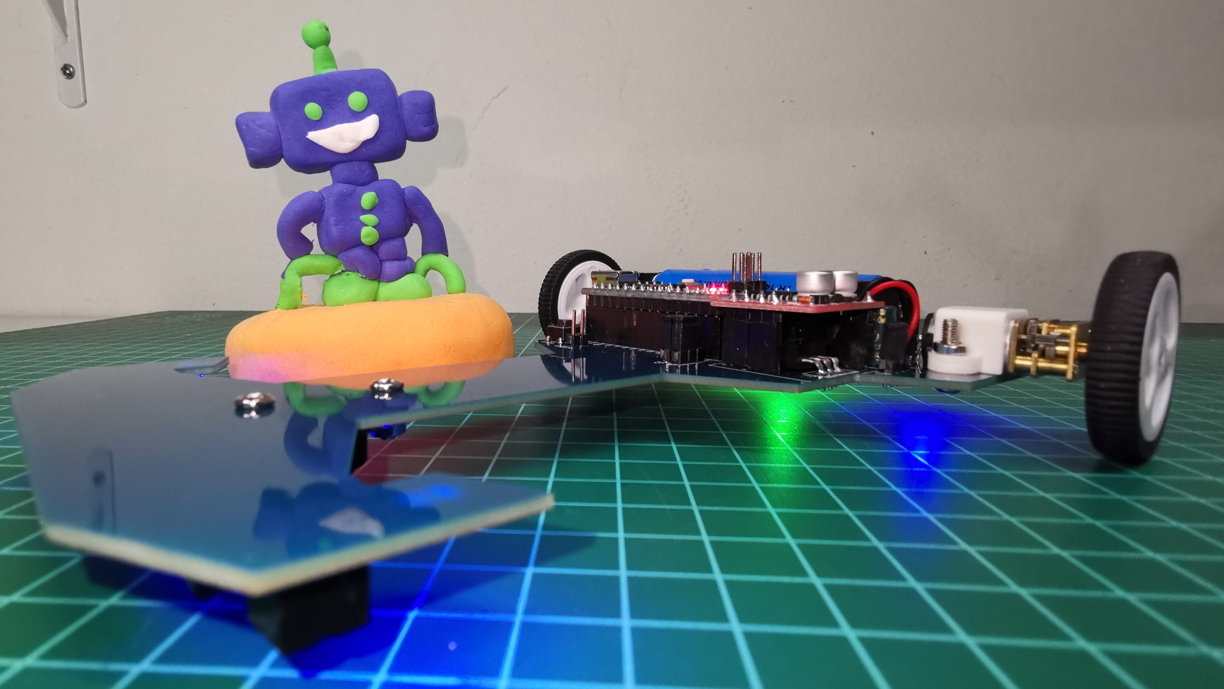
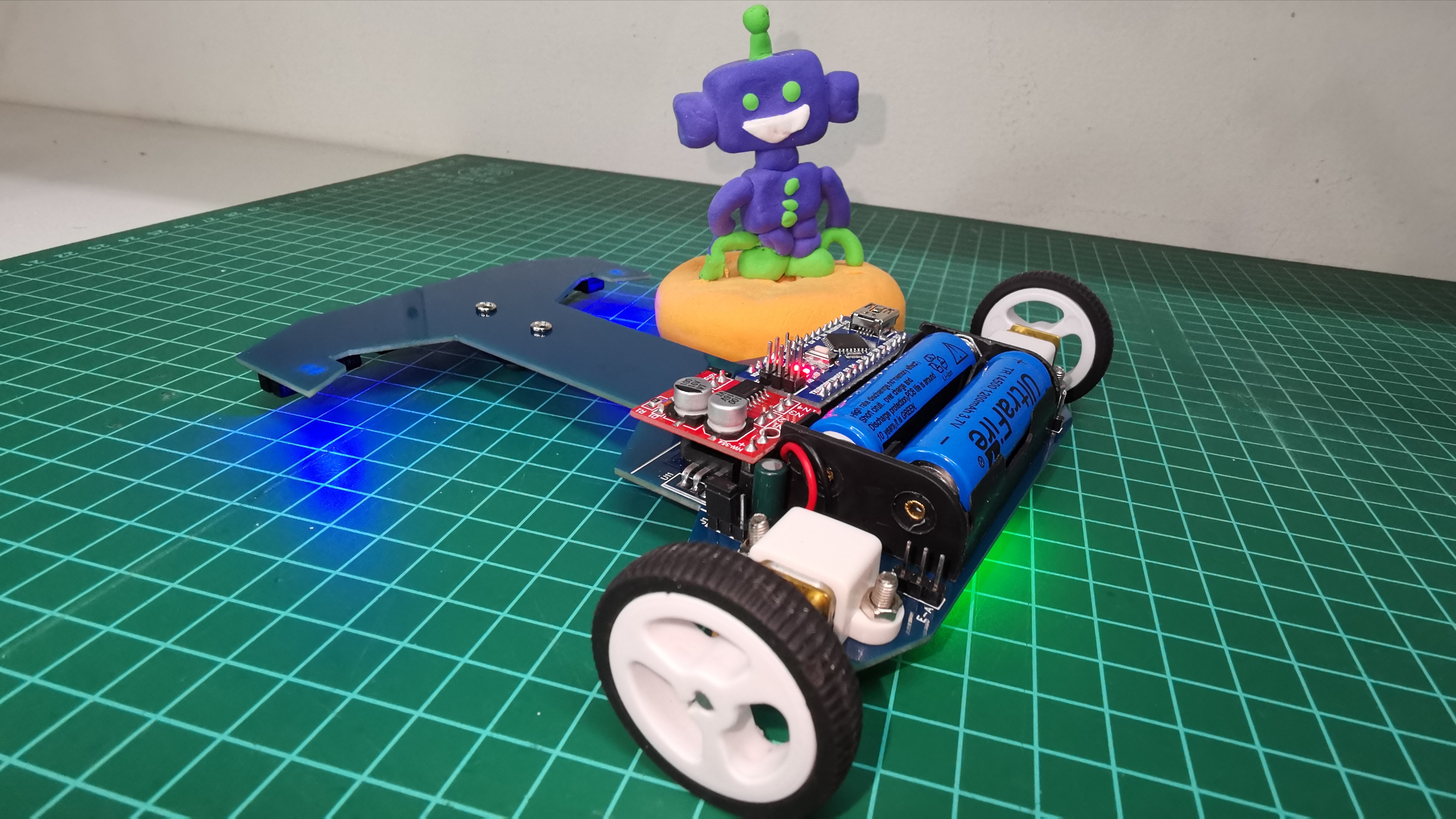
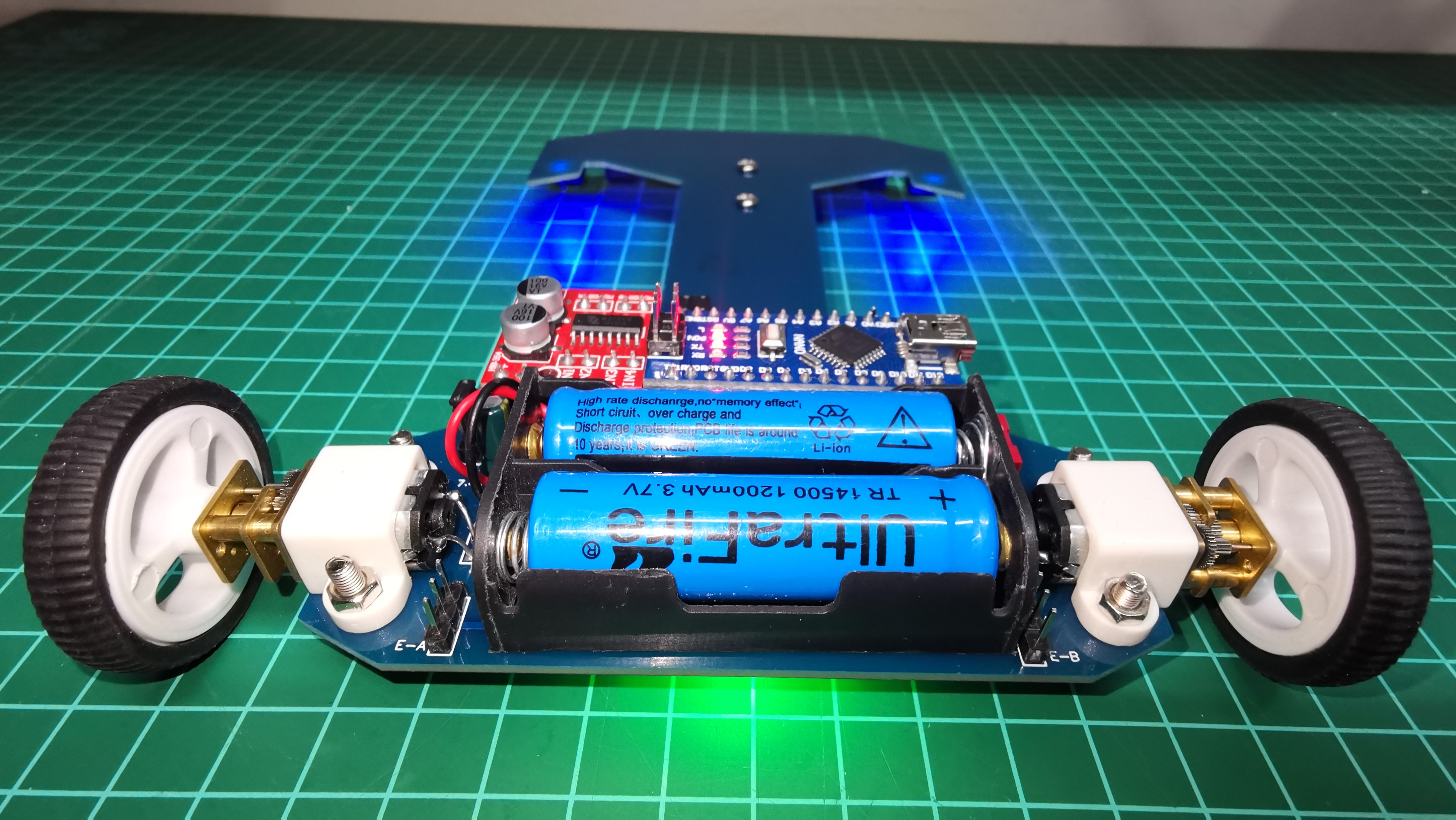
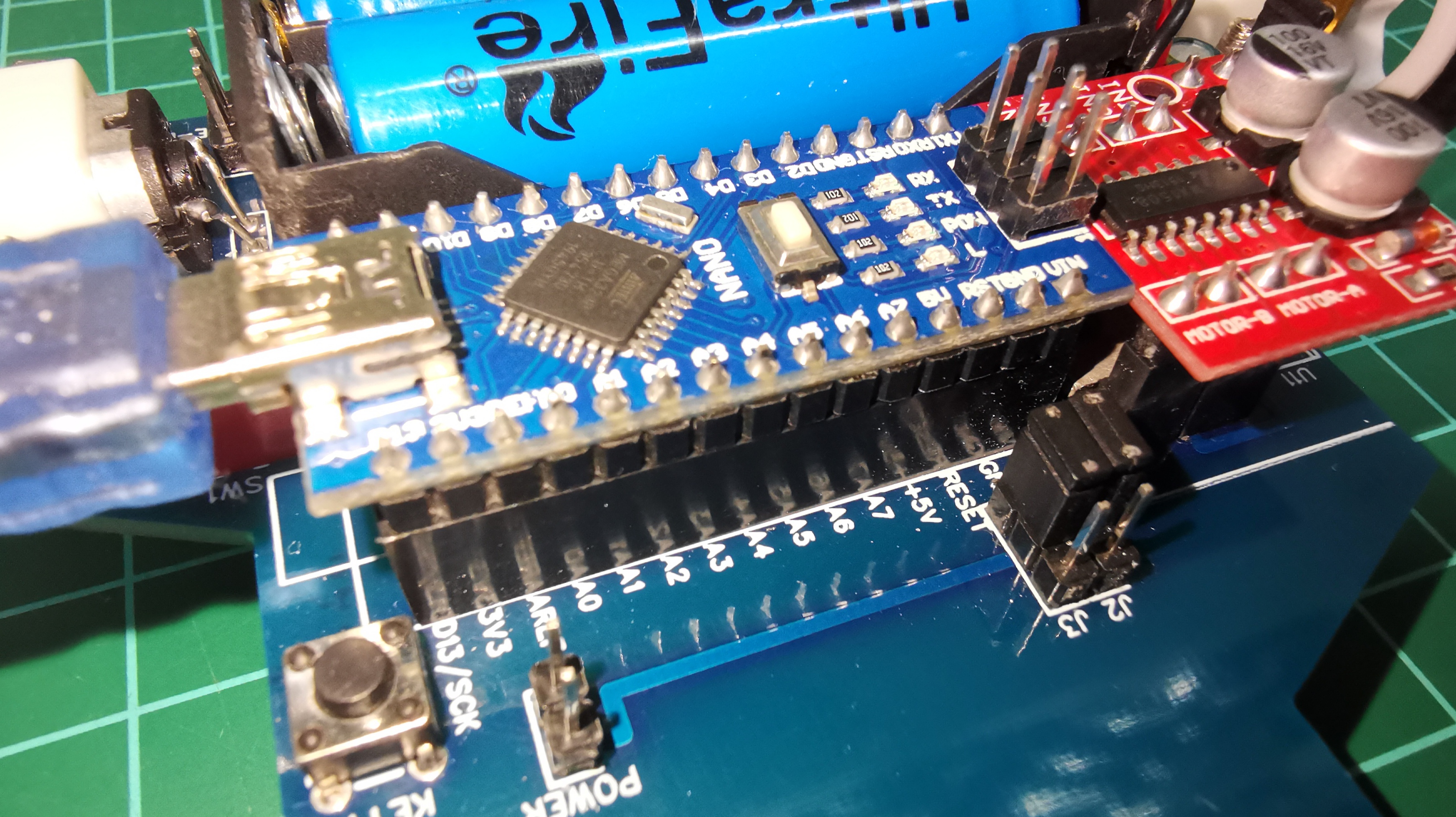
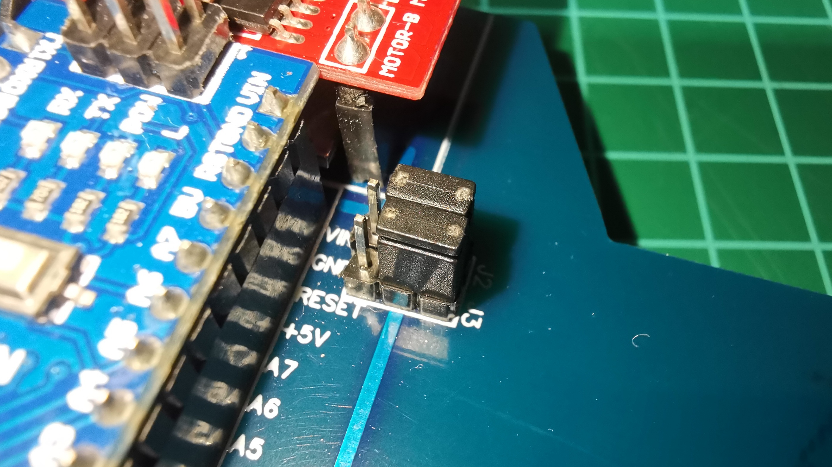
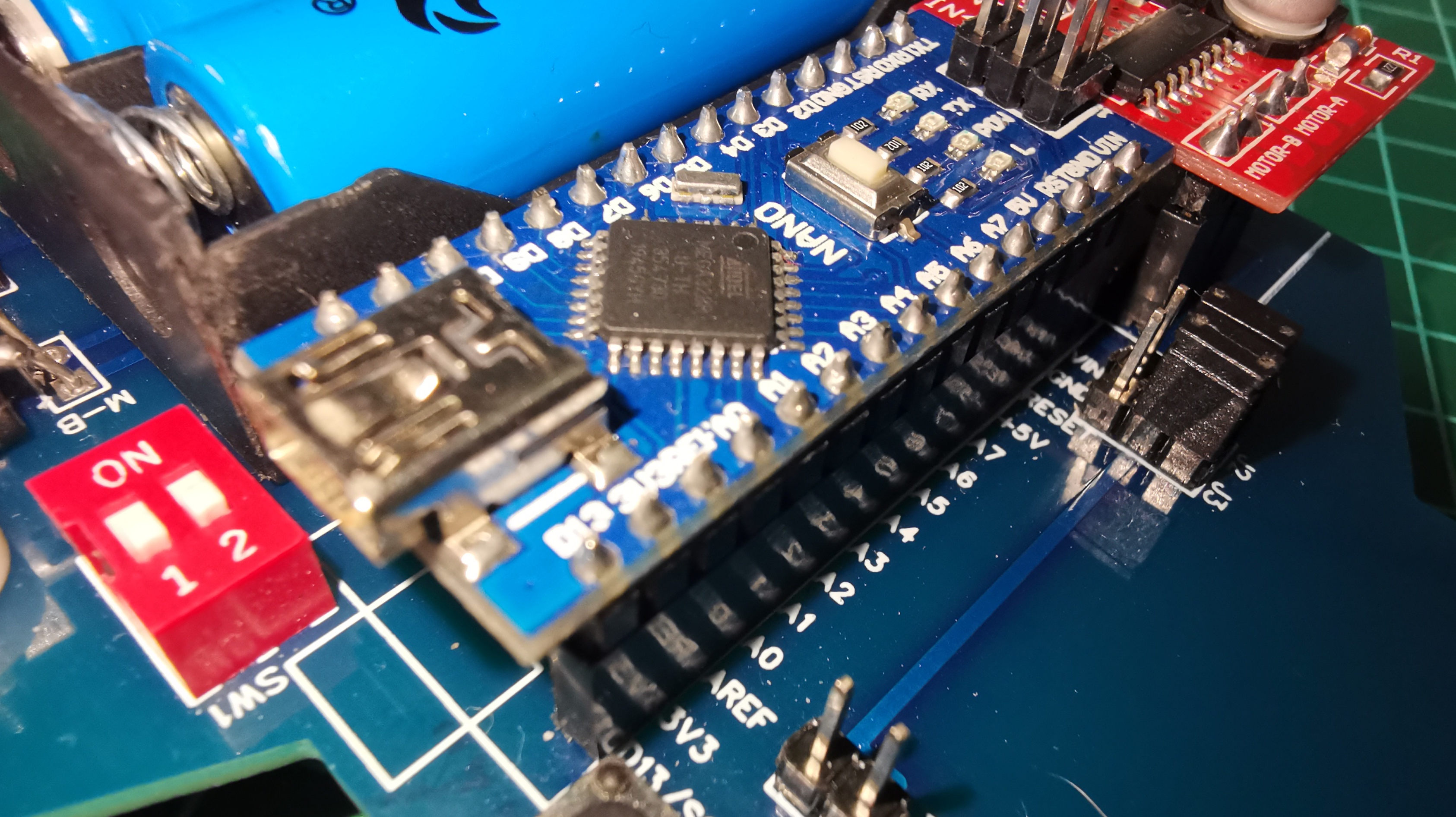
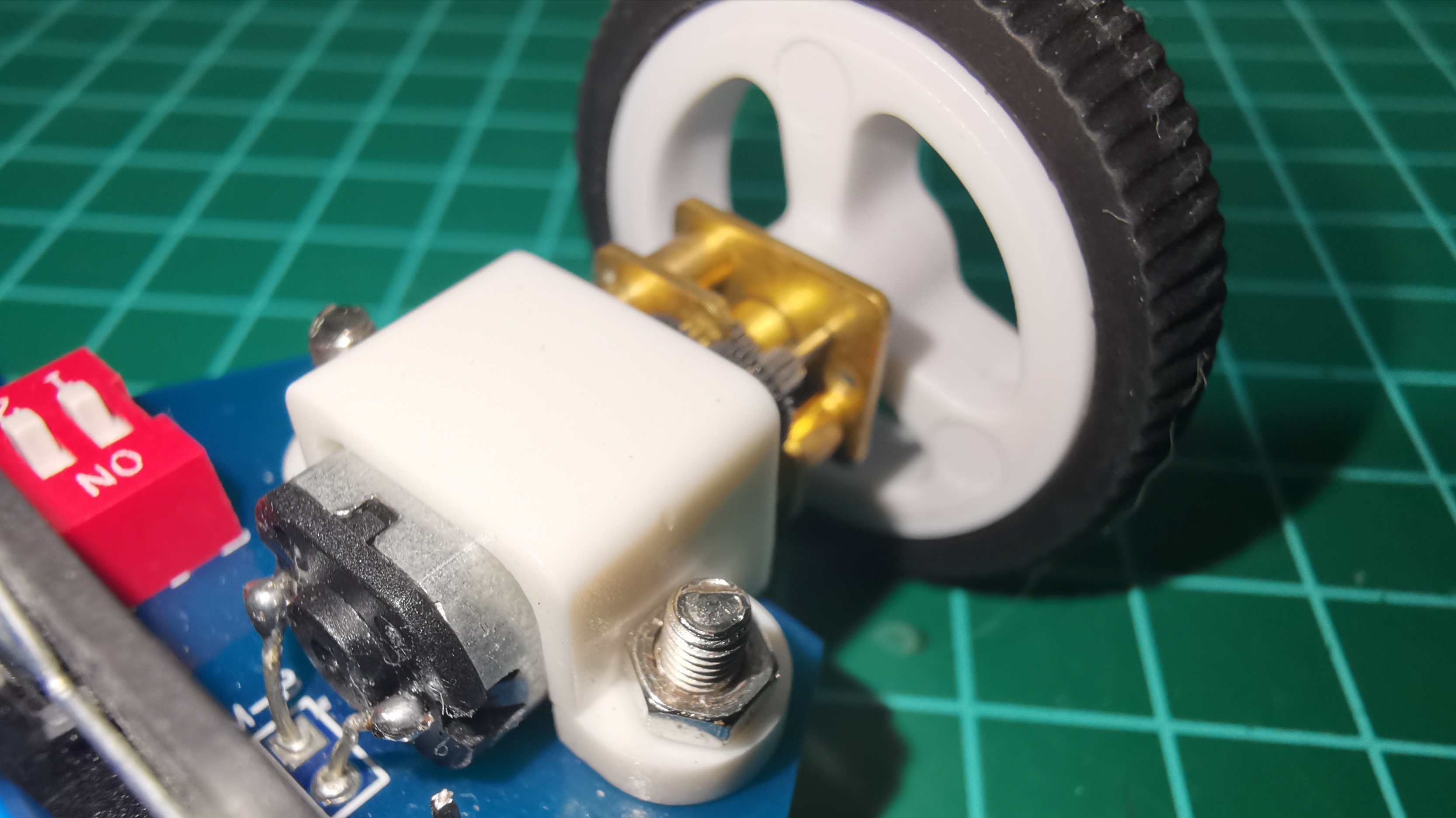
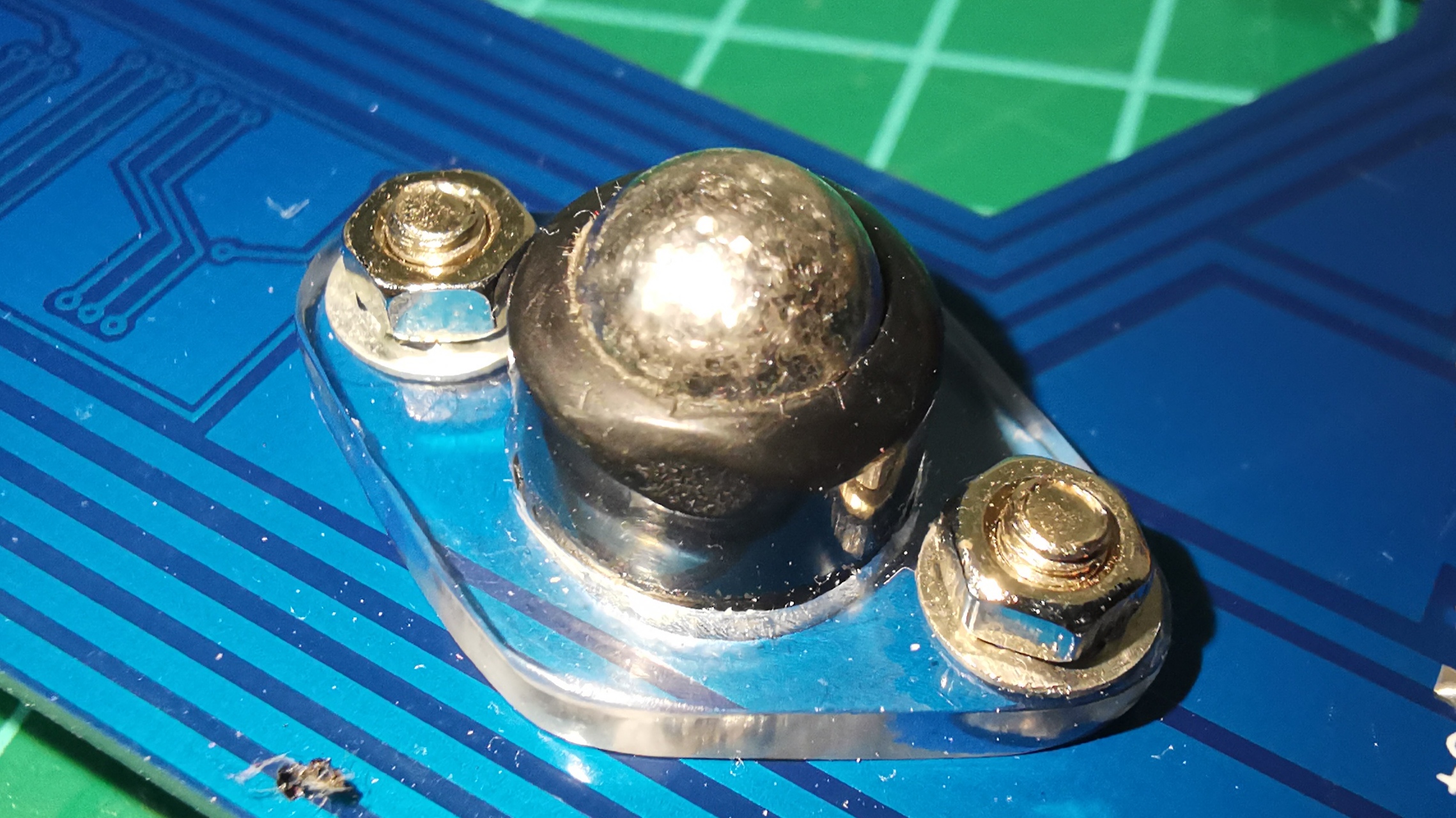
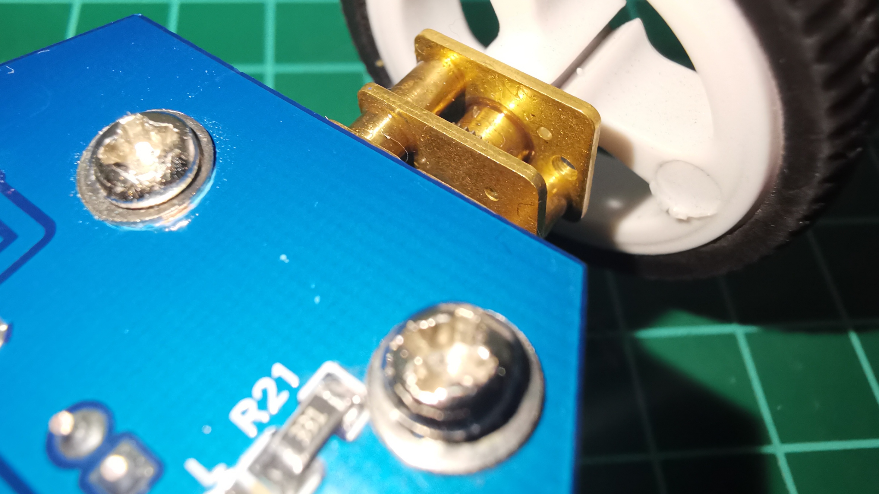
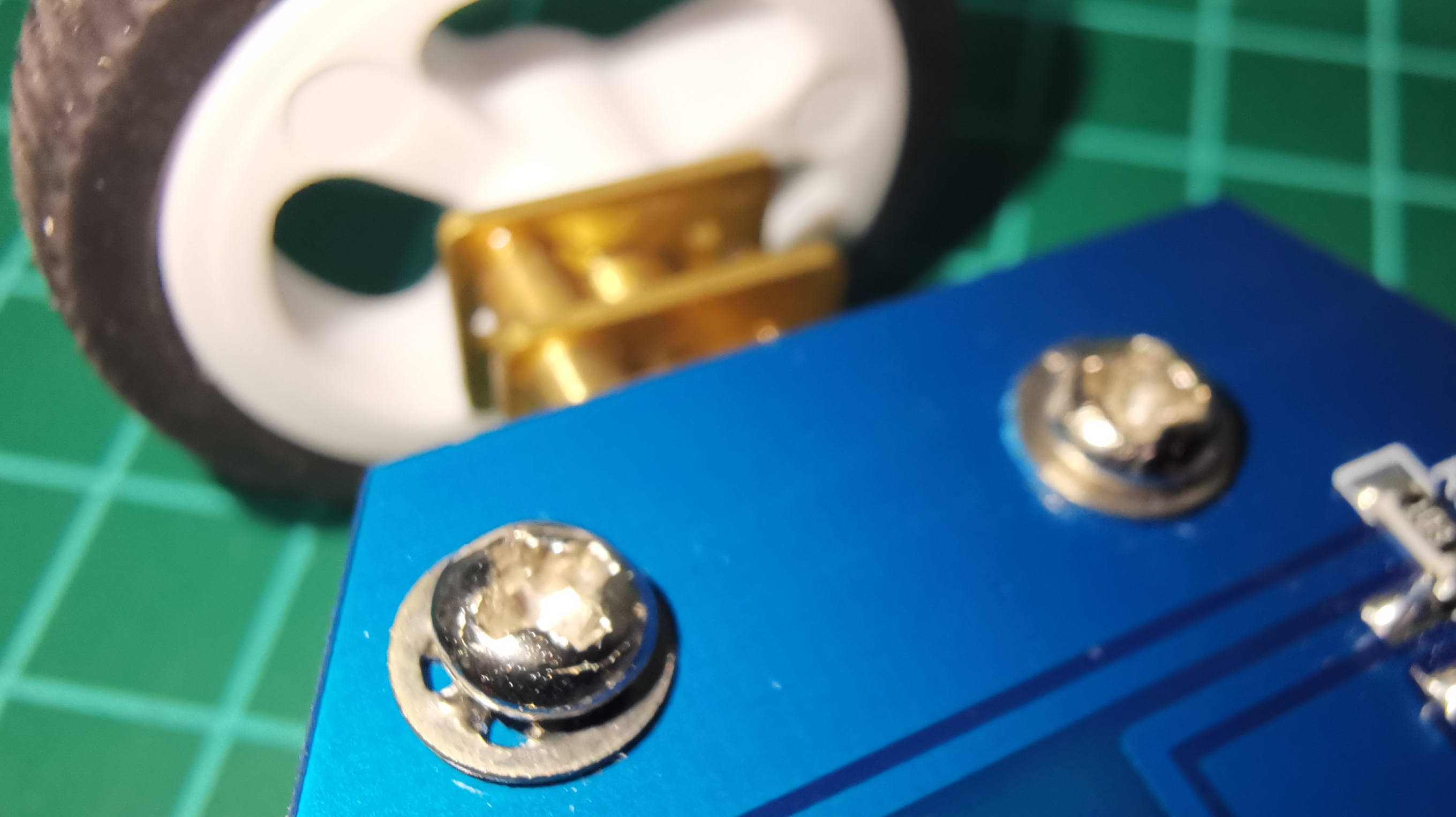
In the final stretch and already with the total of pieces, I show the assembly of my first Speed Follower Robot.
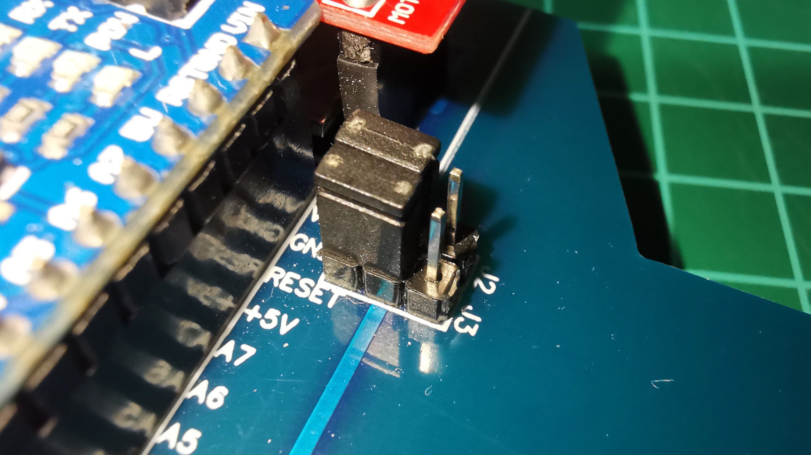
Finally and with a lot of effort I already have the fully built prototype, I show below how to load the code (Code Load Mode), how you can test the sensors and of course the tests on the track. Very happy with the operation, the test code manages to control the code very well. I have used a PID (Full) algorithm to smooth the corrections and regain the course of the line. Since everything can be improved, I will continue to play with the code to achieve a more efficient version.


As a complement, I did the simulation of this robot in the Webots application. It is still in the process of improvement but I share this video so that you can appreciate a way to perform mechanical and logical tests (Code) to control a robot in a virtual environment and that helps to understand the operation of a physically built robot.
Code to control the Speed Line Follower Robot V4
https://github.com/DrakerDG/Speed-Line-Follower-Robot/blob/master/Speed_Line_Follower_Robot_V4.ino
